Category Archives: Valve & electronic theory

How does a valve work? Pt2

In Part 1, we looked at the physics of how a valve is constructed and how it operates. In this session, we will look at a simple valve amplification stage – typical of one pre-amplifier stage in a guitar amplifier.

For illustration, here is a diagram of the input stage of one of my Lamington amplifiers:input-stage


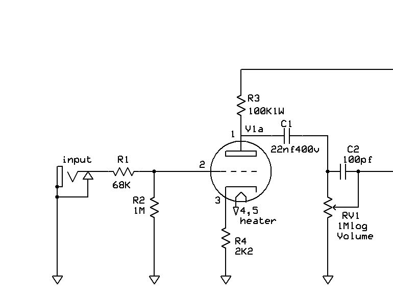
You can see here in this circuit diagram the triode valve (cathode (pin3), grid (pin2) and anode (pin1)) wired in such a way that this stage provides gain (read an increase, or amplification of the input signal).

We saw in part one that a small change in voltage at the grid results in a greater change in electron flow (current) through the valve from the cathode to the anode. We also used the analogy of a valve being like a tap controlling the flow of water through a hose. For a valve to function correctly, it needs to be “biased” at a certain current (flow of electrons) through the valve. To use the tap analogy, this is like setting the tap at halfway between off and on. To “bias” a valve, we need to set up the circuit so that there is a certain voltage between the grid and cathode. This “bias” voltage will be different for different valve types. In this preamplifier stage, the bias is set up by placing a smaller resistor (R4 in this circuit) so that a small voltage is developed across it which provides the bias. This form of bias is called cathode bias.

Getting back to the operation of the preamp stage, you can see that a guitar is connected to the grid via R1 and R2. The signal from the guitar controls the flow of electrons through the valve causing a larger signal voltage to be developed at the anode of the valve. This increased (amplified) signal is fed through  C1 to the volume control and then to the next stage of the amplifier.

That’s probably quite a bit to be digested at this point, but I hope that it is helpful and clear. I welcome any questions or comments below!

More to come!

How does a valve work? Pt1

One of the things we look at at the Valve Heaven Amp School is explaining how a valve (also known as a vacuum tube) works.

Gaining a basic understanding of the inner workings of a valve is very helpful for a guitarist. The operation of a valve is at the centre of how an amplifier works, and getting to know how a valve works helps you to get the best out of your amp!

Here are some images of different valve types: Valves

You may have seen these glass and metal marvels inside your amp. But how do they work?

If you look at a valve in operation, you will see a reddish/orange glow inside the valve. This is the dull red cathode which is heated to a high temperature causing electrons to be released from the surface of the cathode. These electrons form a “cloud” around the cathode. The second element that can be easily seen inside a valve is the metal cylinder or box structure called the anode (or plate if you live in the US). This metal anode is connected in your amp to a source of positive high voltage, and this anode being at a positive potential attracts the negatively charged electrons around the cathode towards it. But there is a third element inside the valve that makes a valve such a powerful device – the grid. Wound in a spiral around the cathode, the grid acts to control the flow of electrons between the cathode and the anode. It operates like a tap in your kitchen – turn the tap off, and there is no water flowing – open up the tap and more and more water flows.

This image clearly shows the internal workings of a valve:

Beam_Power_Tube_Cutaway_Spbg57You can see the heated cathode which emits electrons. These electrons are attracted to the positive anode (or plate). But between the cathode and the anode is the grid (in this diagram of a power valve, there is a second grid, but we will come to that in a later tutorial), and the voltage applied to the grid controls the flow of these electrons. But even more importantly, a small change in voltage at the grid causes a greater change in electron flow meaning that the valve becomes an “amplifying” device. This capacity to amplify or increase the signal makes the valve a powerful device, able to amplify the signal from your guitar and drive power into your speaker.

That’s it for now – Part 2 of this series will look at different types of valves, and how they operate in your amp. Feel free to ask any questions below – I’d love to hear from you!

A very cool amp design tool

For those who have not yet seen it, Duncan Munro has available a very cool amp design tool at his website:

http://www.duncanamps.com/tsc/

The freeware Tone stack calculator program allows you to play with a range of virtual tone stack circuits – you can see several tone stack circuits from Fender, Marshall, Baxandall etc and adjust each “virtual” component to see how it changes the response of the tone stack.

Here is what it looks like:

TSC

I encourage anyone to download it and “plug in” your favourite tone stack and see visually how each component shapes the sound. I use TSC on a regular basis to check different tone stacks I am planning for different amp designs – recommended!