All posts by Grant

Another TV Special amp

A long time ago, I posted the design for an amp on an Australian forum that used valves that were developed for black and white TV service. It has surprised me that there have been nearly 12,000 views of the TV Special thread. Perhaps the interest in this amp has been fueled by large collections of old TV valves that have little use beyond their original application in TV service. The fact is that by far and away the largest consumption of valves (vacuum tubes) in history has been in consumer electronics – TV, Radio and record players. This has resulted in many valves used and NOS still being available very cheaply on Ebay and other online sellers.

My TV special amp used combination valves developed for video amplifier/sync separator application in B/W TVs. In addition, the TV Special also used a 6BX6 TV IF amplifier valve in the preamp. My Gilly amplifiers took advantage of another cheap TV valve – the 6GV8, which was used in the vertical deflection section of a TV set. The reality is that a valve is a valve, and beyond application in TV or Radio service, any valve can be used for other applications as long as their characteristics are suitable. It might surprise some to discover that the well regarded 6V6 power valve was used also as a vertical amplifier in TV sets. My own collection of TV valves continues to grow due to bargain purchases on Ebay, Amateur Radio Hamfest bargain buys and shed clearances. As a result, I thought I’d develop another “TV Special” amp.

As I was keen to make this a “junk box” build, I first decided to use my tried and proven 50W downlight transformer as an output transformer as I have heaps of them here. Having made this choice, the design then became a simple 5W single ended amp. As the output transformer reflects a 3.2K load to the output valve, I looked through my valve collection and datasheets to find a TV valve that is suitable for driving this lower impedance load.
A suitable candidate is the EL86/PL84. This is a similar valve to the EL84 and was developed to deliver more power with a lower HT supply. It was used in sound output and vertical output application in TV sets. The PL84 is the series heater version of the EL86.

Here is a page from the PL84 datasheet. You can see that this valve is ideal for the planned amp to drive a 3.2K load 

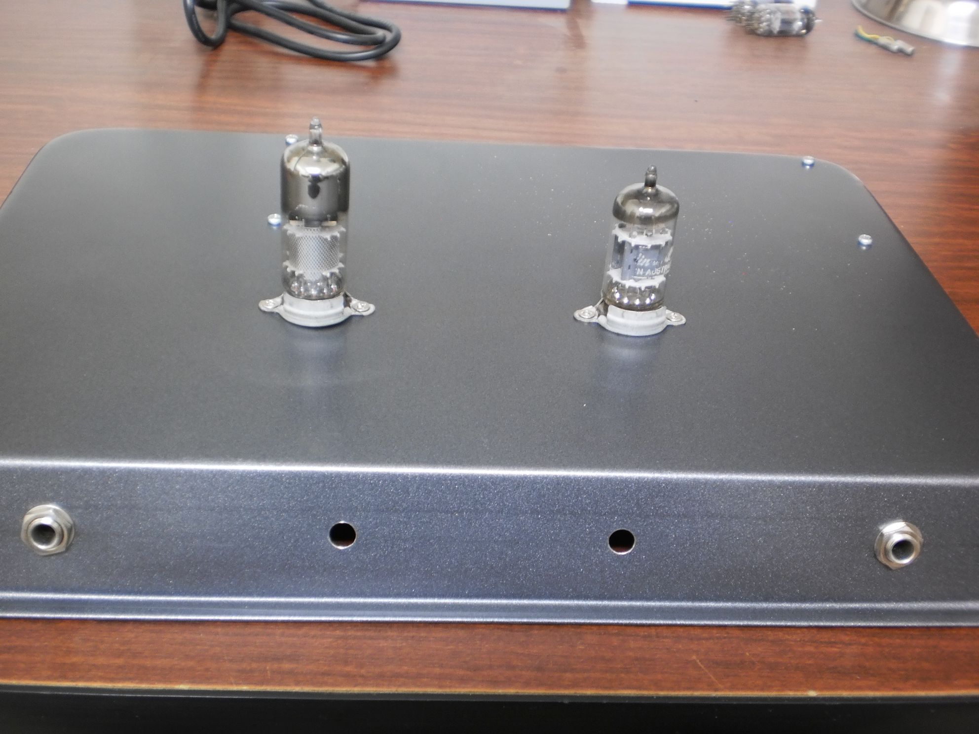
The parts for this amp now began to be gathered 

Having settled on an EL86/PL84 TV valve for the output stage, I was keen to continue the TV theme with a preamp valve that was also developed for TV service. In addition, I wanted to use series heater valves for this build as they simplify a power supply build. Series heater valves were developed for TV use in Europe and the US. Instead of the more familiar arrangement of 6.3V heater valves sharing a common heater voltage (6.3V), series heater valves shared a common heater current (typically 300mA). The valve heaters were designed with “controlled warmup” – meaning that they all came up to operating temperature at the same time and so balanced the heater currents.

So having selected a PL84 series heater output valve, I chose a PCF802 preamp valve. The two heaters in series could be supplied from a 24V transformer winding. The PCF802 was developed for low hum and microphony for TV line oscillators and so is ideal for the preamp in a guitar amp. Details here: http://www.r-type.org/addtext/add124.htm

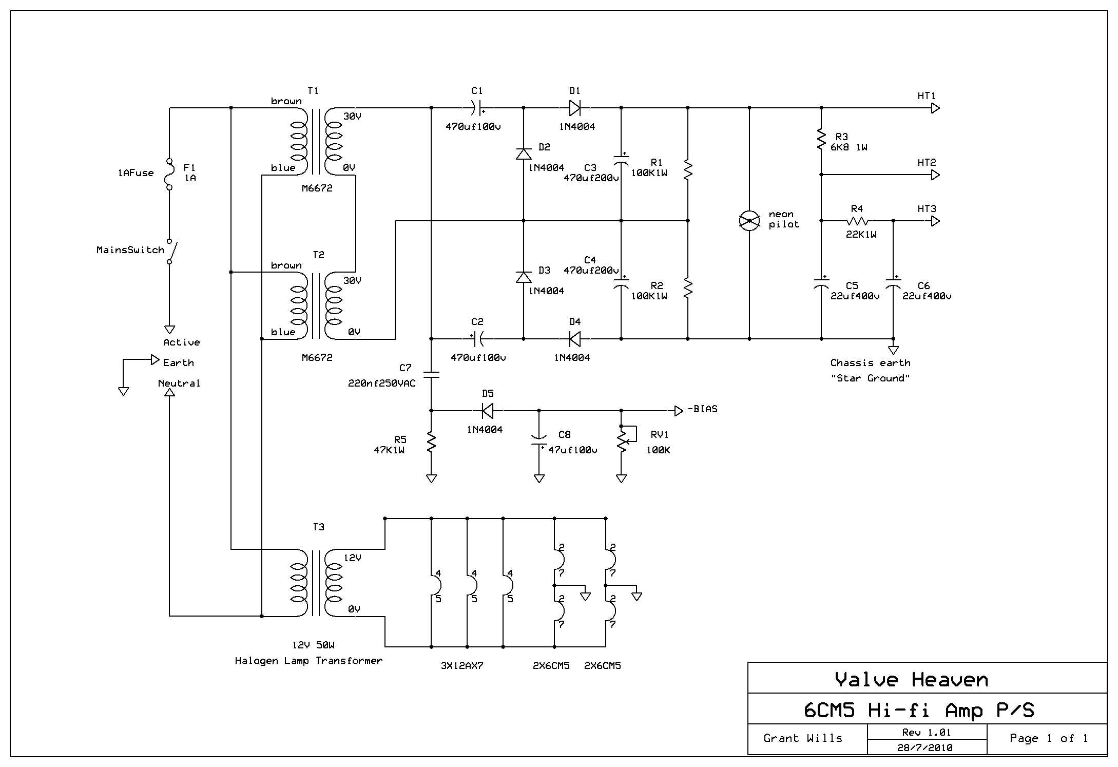
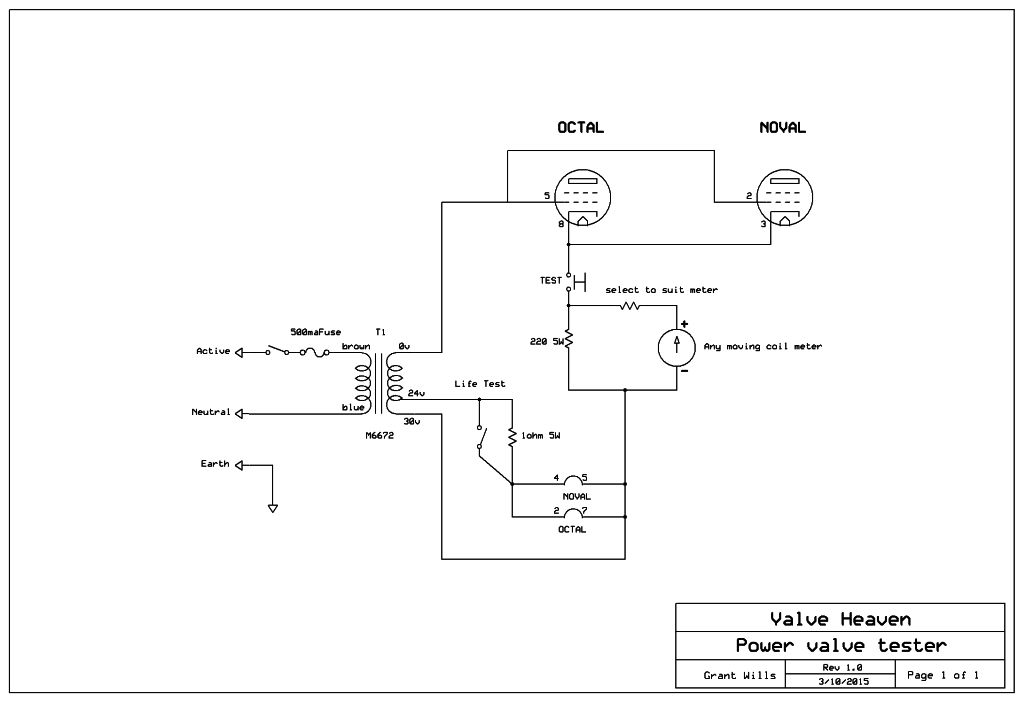
Here is the schematic for the power supply for this new amp:

One power transformer does double duty to generate the HT for the amp and also provides power for the valve heaters.
An old Australian made A&R 240 to 48V C.T. transformer feeds a voltage quadrupler to generate around 250V DC HT. As mentioned the PL84 and PCF802 are “series heater” valves sharing the same current rating of 300mA. In this amp the two heaters in series require a total of 24 volts which is taken from the “cold” side of the multiplier input and the transformer centre tap. The PCF802 preamp valve heater is connected to the cold side of the multiplier input to minimise hum induction. This means that the valve heaters “float” at 1/2 HT (about +125V DC) but this is well within their max 200V heater to cathode voltage rating. A bonus of the valve heaters being elevated at a higher voltage than the cathodes is that hum is also minimised.

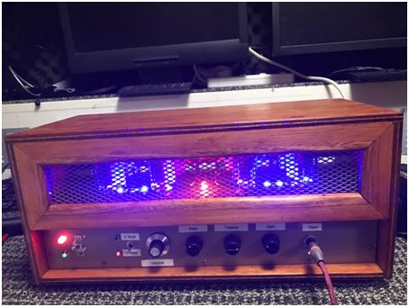
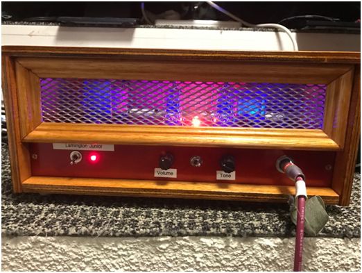
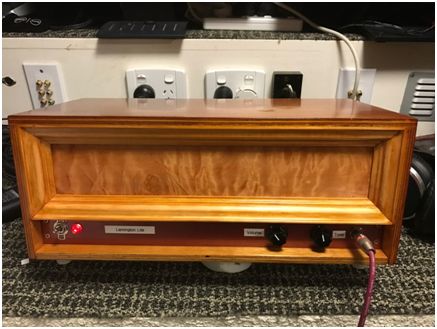
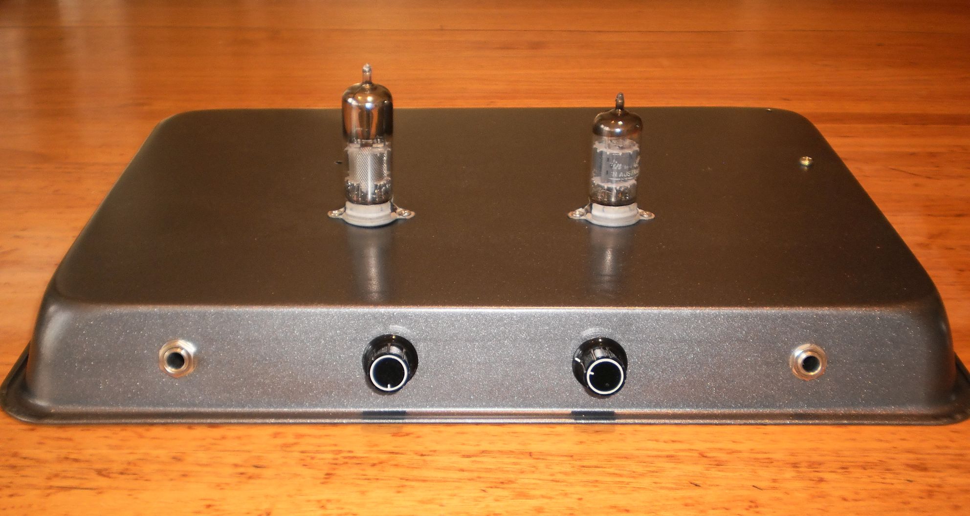
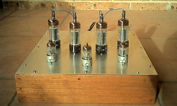
Here is the finished amp:

There is certainly not much to it – a couple of valves and transformers and one volume control. I have been pleased with the result – approximately 5W of output from the PL84. The one thing that stands out is how quiet the amp is – the amp is dead quiet until the volume is fully advanced and only then a small amount of hiss. This has probably been the quietest amp I have developed. I think this is due to the largish 470uf caps in the power supply but mostly due to the elevated valve heaters. Certainly not bad for a single ended amp as they lack the inherent hum rejection of a push pull amp.
As far as tone goes it sounds quite authoritative for its 5W of power with a strong mid range and rather nice overdrive when fully driven.

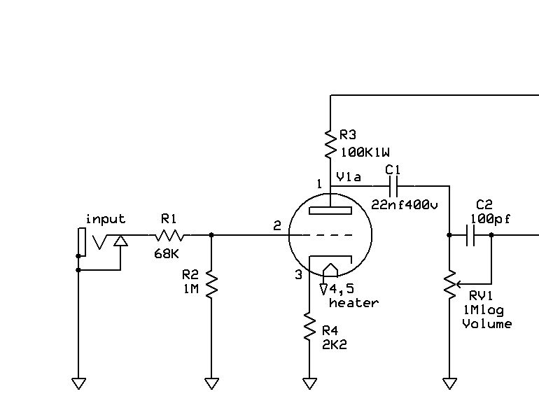
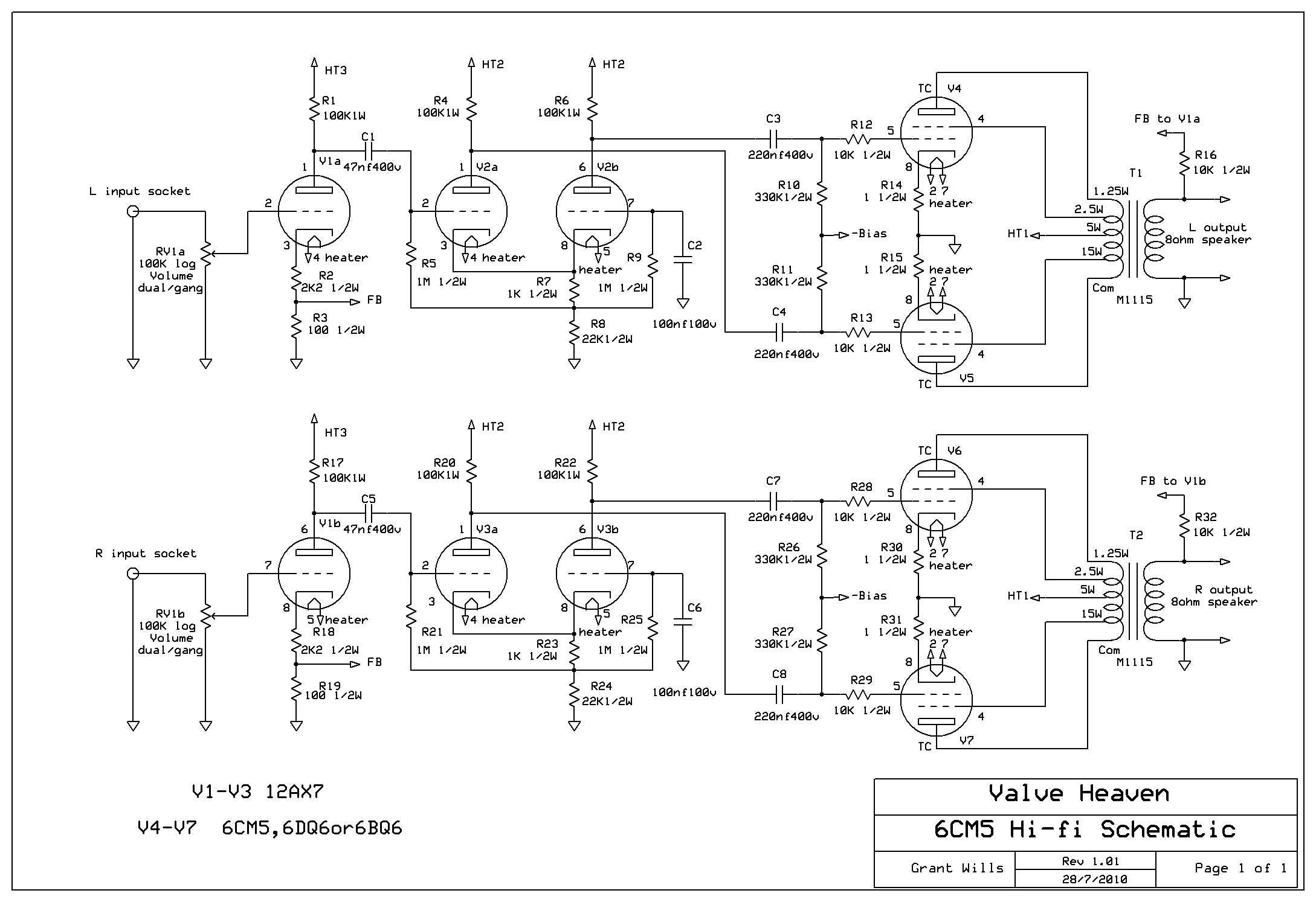
Here is the schematic for the amp:

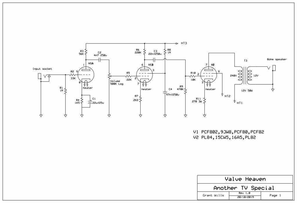
The PL84 in the output stage can be seen driving the halogen output transformer. The preamp uses the PCF802 triode/pentode as mentioned. I have also listed several other valves that can be substituted for the PL84 and PCF802. The PL82 (16A5) can be used in place of the PL84 and a PCF80 (9U8) for the PCF802. I decided to use a preamp arrangement using the triode section of the 6U8 triode/pentode valve essentially as a lower gain booster driving the pentode section which provides most of the amp gain. Both the pentode stage and the output valve have no cathode bypass capacitors and it is suggested that this helps shape the overdriven tone . Having said all that, it is certainly a very simple amp with quite an amount of output power and great tone – a good outcome from some old TV valves 

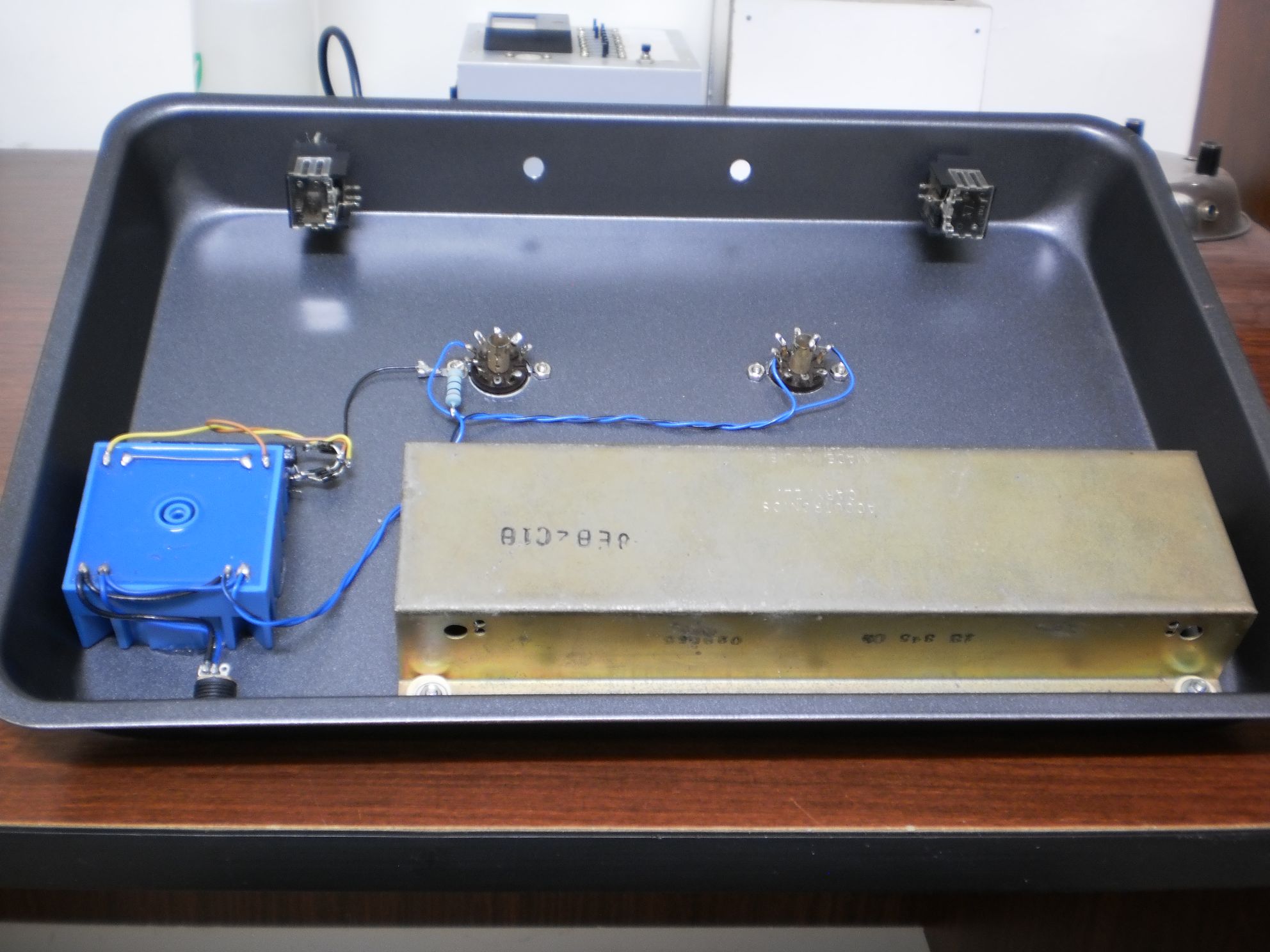
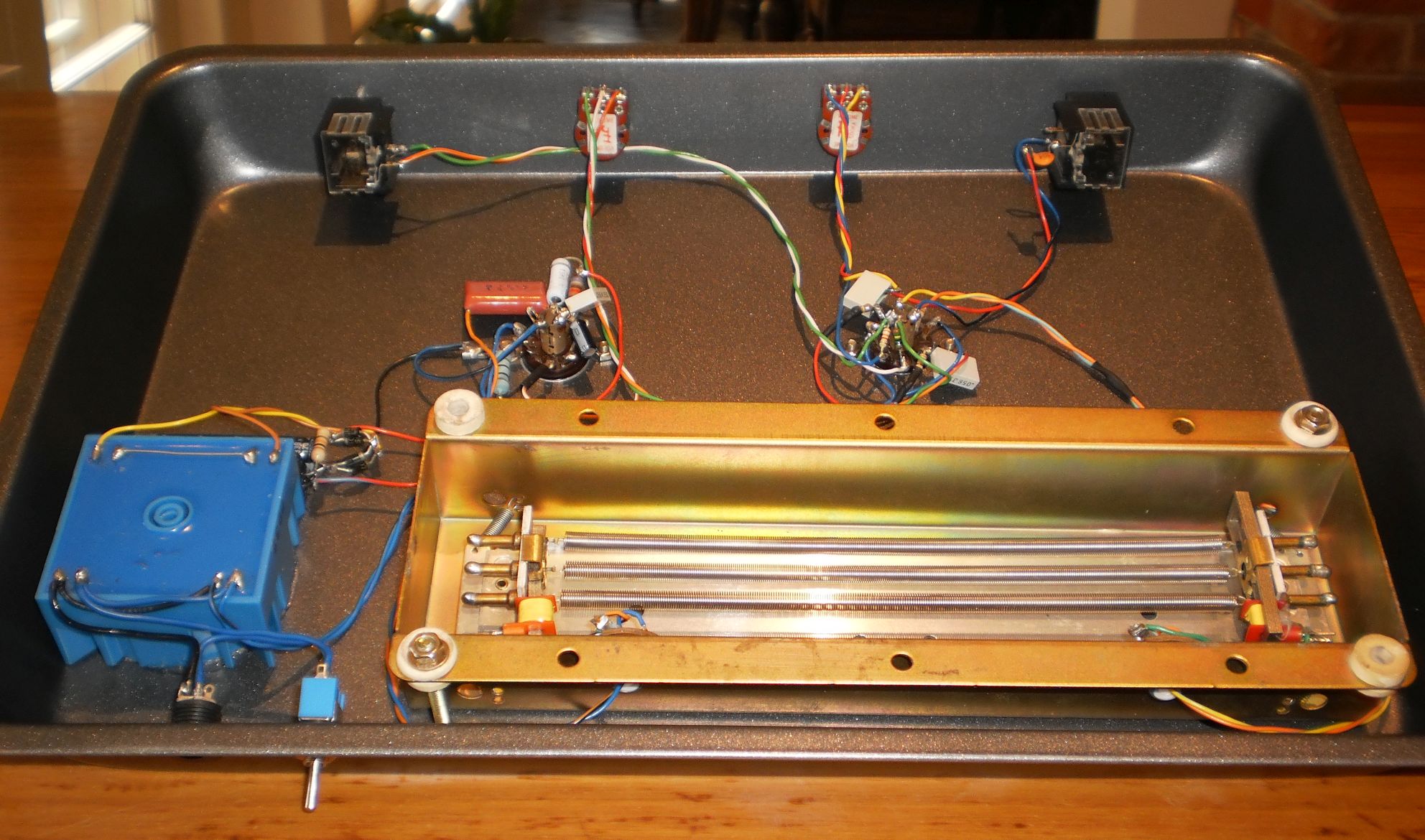
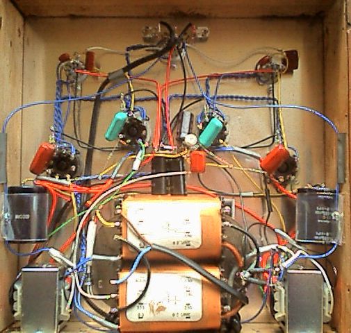
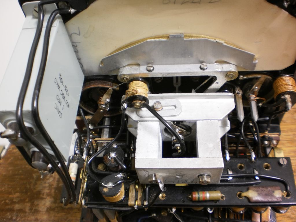
Here is the amp underside – again, not much to it. The quadrupler voltage multiplier and components clustered around the two valve sockets.

What common issues come up when building a valve guitar amp?

As Lamington amp builders progress through the construction of their amplifiers, some common questions arise. I thought it might be helpful to discuss some of these questions to assist other diy amp builders.

The first issue that often comes up is identification of the components. For a newcomer, it can be confusing to identify capacitors, resistors, diodes …… picofarads, microfarads, megohms etc!

The first step is to identify the resistors. They look like this:

Resistors

You can see that most resistors have their value marked with a colour code. To “read” the value of a resistor, here is a colour code chart:

res-code

LAYOUT AND WIRING

Another issue that arises in amp building relates to layout and wiring.

From time to time, I am contacted by builders of my Lamington amps who report that their amp works but has noise or other extraneous hash in the output. When the volume is increased a whistling or rushing sound is heard. This is almost always caused by layout and wiring issues. What is not immediately evident in an amp is that the most sensitive parts of an amp can pick up the large signals around the output stages. If the wiring in the amp is not short and direct output signals get picked up by the input stages causing instability and oscillation much like when a microphone is placed too close to a speaker in a PA system. If your amp demonstrates these symptoms, spend time shortening unnecessary long leads. This will sort out the issue in 95% of cases.

How does a valve work? Pt2

In Part 1, we looked at the physics of how a valve is constructed and how it operates. In this session, we will look at a simple valve amplification stage – typical of one pre-amplifier stage in a guitar amplifier.

For illustration, here is a diagram of the input stage of one of my Lamington amplifiers:input-stage


You can see here in this circuit diagram the triode valve (cathode (pin3), grid (pin2) and anode (pin1)) wired in such a way that this stage provides gain (read an increase, or amplification of the input signal).

We saw in part one that a small change in voltage at the grid results in a greater change in electron flow (current) through the valve from the cathode to the anode. We also used the analogy of a valve being like a tap controlling the flow of water through a hose. For a valve to function correctly, it needs to be “biased” at a certain current (flow of electrons) through the valve. To use the tap analogy, this is like setting the tap at halfway between off and on. To “bias” a valve, we need to set up the circuit so that there is a certain voltage between the grid and cathode. This “bias” voltage will be different for different valve types. In this preamplifier stage, the bias is set up by placing a smaller resistor (R4 in this circuit) so that a small voltage is developed across it which provides the bias. This form of bias is called cathode bias.

Getting back to the operation of the preamp stage, you can see that a guitar is connected to the grid via R1 and R2. The signal from the guitar controls the flow of electrons through the valve causing a larger signal voltage to be developed at the anode of the valve. This increased (amplified) signal is fed through  C1 to the volume control and then to the next stage of the amplifier.

That’s probably quite a bit to be digested at this point, but I hope that it is helpful and clear. I welcome any questions or comments below!

More to come!

An in depth review of the Lamington amp series

I recently received this in depth review from Colin P who has built just about all of my Lamington amp designs!

It makes an interesting read as Colin has learnt a great deal about valve amps along the journey of building Lamington amps.

Hope you find it interesting as well!

“First Lamington build: 18W
As a first build the Lamington 18 watt amp is not something you want to be attempting with no help at all, especially if you have no experience with valve amps construction. I tried using only the schematic as a guide, and three knock-down re-builds later I bought the construction manual from Grant – So I can honestly say this is money well spent.

Although the finished amp has a little background hum (because of my sub-optimal tube placement) the result of following the manual’s wiring practices is a great clean sounding amp with loads of headroom and excellent overdrive tones. I opted for the 5/15 switch and it’s loud through a 1×12 cab with a Celestion vintage 30 – even at half volume on 5 watts. Tone control is smooth, and with the gain up high this amp is a screamer that compares very well to some of the big brands at a fraction of the cost.

I built the chassis in to a 9mm marine ply box using GutterGuard for the front grille, added red and green pilot lights to show the 5w and 10w options and added a blue LED strip for some bling.
I also had a local machine shop knock up the chassis out of a sheet of 1.5mm aluminium so it’s not a true Lamington because I didn’t source the chassis from K-Mart – And 150 coats of shellac always looks good on a decent slice of timber – Here’s a photo.:

colin-lamington

Next Lamington build: Lamington Junior (2w)
I already had two Lamington amps done, and was looking for something smaller to use in my 3×3 music room when I saw the Lamington Junior design which became the subject of my 3rd Lamington build.

For this project I chose Grant’s point-to-point methodology which is much lower in cost, and it went without saying that I bought the build guide- Just to make sure everything was done right.
For the chassis I used a spare piece of 1.5mm aluminium sheet the same size as an A4 page, with a couple of extra pieces pop-riveted on to make the front and back panels – So it’s not strictly a true Lamington Junior either, but I will take the hit on that one..
Although it is a small amp it is also surprisingly loud, and sounds great through both my 1X12 Eminence and Celestion cabs. Tone control is also very precise, and cranked up this amp sounds fantastic with my Les Paul and my Strat. It’s a bit small for gigs but it’s an excellent practice and studio amp and it’s easy to build – even if you do the metalwork from scratch like I did.
This one has the power switch to drop the output to 1w – and from my experience there is not a whole lot of difference – They are both loud…

After construction and checking of all the wiring, component values etc the amp came up first time with no issues and I can honestly associate that with Grant’s build guide which is very easy to work with.
In case I haven’t said it before: “Be sure to buy the build guide” – It’s money well spent and it takes the hassle factor out of the equation when you are trying to figure out why things are not working, especially if you are new to tube amp construction..

Here is my Lamington Junior – Bling and all…

colin-lamington-jnr
Another Lamington build: Lamington Lite (10w)
I knew I was going to enjoy the Junior but I also wanted something a little larger that I could use for small gatherings where a PA was not necessary, so I started a Lamington Lite build just as I was finishing off the Junior. Using the same point-to-point technique as Grant’s other designs this amp also worked off the bat and I have to say that it has become one of my all-time favorites.
It is simple to set up, the big clean tones are magical, and the overdriven sound is way too good for an amp that costs just a couple of hundred dollars to build. I bought a second set of tubes just in case, so if anyone has spare pair of Halogen transformers I want them !!

The chassis is made out of another piece of scrap aluminium with sides riveted on, and the halogen transformers came out of a friend’s roof – So it cost almost nothing to construct, and it’s not much bigger than the junior.

The thing I like most about this amp is the clean headroom which is crystal clear– it needs to be well up on the volume dial before it starts to break up so if you are looking for a great little amp that doesn’t cost a bomb this is the one to go for.

I also built mine in to a marine ply box with a billion coats of shellac for a mirror finish (about standard these days), but with this one I opted for a quilted maple veneer on the front panel instead of the LED bling. There is also a panel on the back but I have allowed for airflow so it does not get too hot inside..

colin-lamington-lite

For reference here’s a gaggle of Lamingtons  on top of an Eminence Legend 1×12″

colin-lamingtons

The Lamington Reverb – a better valve reverb unit

I have been kicking around the idea of a “Lamington” stand alone spring reverb unit for a while, and recently began a build.
The inspiration for the design came from a Channel Road Amplification tech paper found here: http://www.channelroadamps.com/articles/reverb_driver/

Driving a reverb spring tank presents some challenges. The commonly used driver circuit drives a low impedance tank via a small transformer. While this works, it provides constant voltage drive which is not the best way to drive a spring tank. It results in poor high frequency response due to the inductive nature of the drive coil. A much better way to drive a tank is with a constant current drive circuit. This results in a wide band response from the tank.

Inspired by the Channel Road paper, I looked at building a stand alone reverb unit. Using a high impedance tank and a constant current pentode driver that eliminates the drive transformer, it is possible to build a simpler (and superior) spring reverb unit . In addition, a plugpack power supply similar to the one used in the Lamington Junior amp can be used to simplify the power supply and make it a cheap build.

More details to come!

Some progress – the chassis was prepared with holes for the controls, valves and spring tank. As mentioned, a 12V plugpack supplies power to the valve heaters and a toroidal transformer steps up the 12V AC to generate the HT for the valves.

An Accutronics 8EB2C1B spring tank was at hand and is ideal for this build with an 800 ohm drive impedance. These tanks are readily available as a spare for the Fender Blues Junior amp both here in Australia and O/S.

lr-1lr-2

Have now completed the Lamington Reverb and pretty happy with it.  Firstly, a photo of the finished reverb unit.
From left to right: input, dwell, mix controls and output.
Also visible is the 6BX6 tank drive valve and a 12AX7 preamp and recovery valve.

lr-3

And an underside photo. Not a lot to it – a 12V to 240V toroidal transformer, the reverb tank, and some components clustered around the valve sockets. You can click on the image for more detail.

lr-4

Here is the schematic for the Lamington Reverb. You can click on the image for more detail.

the-lamington-reverb

It is a simple circuit, but works well.

The input signal is fed to the first gain stage with the dry signal fed straight to the MIX control from the cathode. This first stage drives the current source pentode via the DWELL control. This determines how hard the tank is driven and changes the reverb tone as a result. As discussed, the tank drive circuit is taken from the Channel Road paper and provides current drive directly to the tank eliminating a drive transformer. The tank used in the prototype is an Accutronics 8EB2C1B which is used in the Fender Blues Jnr and is readily available here in Australia and overseas. Its drive coil impedance is 800ohm and is ideal for the constant current driver which is a commonly available 6BX6 (EF80). The output of the spring tank is fed to the other half of the 12AX7 input triode and the output of this valve is fed to the mix control and output socket.

The power supply is a simple arrangement using a 12V 1A plugpack which feeds the heaters and a second transformer which steps up the 12V to a high voltage for the valve HT.

Some construction details to come.

Some comments on constructing the Lamington Reverb.

In building a spring reverb unit, it is very easy to couple unwanted mains magnetic fields into the tank pickup coil causing hum in the finished unit. My approach to have a hum free unit was to use a toroidal step up transformer which has less external magnetic field than an ordinary EI lamination transformer. Also, I positioned the tank with the pickup coil at the other end of the chassis from the transformer. In addition, I found if I inverted the tank further hum reduction occurred.
If you are using an EI step up transformer, I suggest waiting before mounting it. With some extension leads on the transformer, move it around to find the position that induces the least amount of hum and mount it there.
You may note that I have used fairly large values of HT filter caps for the prototype. This was necessary to eliminate any HT hum from being introduced into the unit.Re suitable valves for the Lamington Reverb, the 12AX7 is readily available. The 6BX6 is no longer manufactured, but was used by the squillions in the day in B/W TV sets. It can be substituted with about any RF pentode such as the 6AU6, 6EJ7, 6ET6, 6CB6, EF94 etc
The Accutronics 8EB2C1B reverb tank is readily available from Evatco here in Australia or from Ebay. You may wish to use a longer tank which would work fine in this unit as long as it has a high impedance (600 or 800ohm) drive coil.Re the transformers, the plugpack is a 240V to 12V1A AC unit. The stepup transformer I used is a 10VA 240V to 12V toroidal transformer wired backwards. Just about any low power 240V to 12V transformer could be used – just check its location with respect to the reverb tank as mentioned to minimise hum.

So overall, I have been very happy with the Lamington Reverb – it sounds very lush with no unwanted noise and hum. The ability to vary the drive to the tank with the dwell control is an added bonus to change the character of the reverb tone.

The Lamington amp on “Ultimate Guitar Tone School”

Thought you might be interested to check out the Lamington amp being featured on a new training video just released at ProAudioDVDs. My brother David Wills has recently produced a new online training  course – the “Ultimate Guitar Tone School”.  The Lamington amp is showcased to demonstrate how an amp works, with explanation of the various sections of the amp and how they function.

UGT lamington

Check out the introductory video:

http://proaudiodvds.com/ultimate-guitar-tone-school#about

A 6CM5 hi-fi amplifier

I regularly receive emails with questions about a Hi-Fi valve amplifier design I developed many years ago. The design has been posted on a few websites and I thought it would be a good idea to re-post it here and to add some updated information.6CM5 amp3

Here is the schematic for the amplifier – click on it for full size.6CM5 Hi-fi Schematic

And here is the text that accompanied the original design:

“This is a design for my 15W/channel ultralinear hi-fi stereo amplifier. The front end of the circuit is conventional. The Mullard 5-10 amplifier uses the same phase splitter as I have, and the text refers to it as “a cathode-coupled phase splitter”. The output stage initially used 6L6 valves with a supply of 300V as again I had some on hand, but after quite a bit of experimentation with other output valves I landed on 6CM5 valves. 

As is well known, they are an odd valve to be used for audio applications, and I had several unsuccessful attempts to use them. I thought initially that I’d feed the screens with 1/2 B+ as that is how data sheets suggest you should do (and incidentally how similar line output valves such as 6DQ6 are configured in old guitar amplifiers). However, any attempt to use them in this way caused fairly violent oscillation at ultrasonic frequencies. In addition, I wanted to use them in ultralinear configuration and tying the screens at 1/2 supply did not permit this. The ratings indicate a maximum screen supply of 200v and so I hesitated to use the ultralinear mode. However, after trying several configurations which either oscillated, distorted or otherwise misbehaved, I tried them in ultralinear mode with a fairly high amount of bias (-50v), and they worked really well. They were by far the most linear of any valve I tried and worked well with a fairly low standing current (approx 25ma each) and put out the maximum power (17w). This seemed to justify their rather high heater power requirement. So it seems that it is fine to run these valves with higher screen voltages.

The power supply used an old Philips valve power transformer which was up to the fairly high heater current load (4x 1.25A + 3x .3A = 5.9A) and had a ht winding of 110v which applied to a voltage doubler provided 300v HT. I decided to use fixed bias as it allows higher plate to cathode voltage for the output valves than cathode bias. The technique of getting a negative bias voltage from a voltage doubler is an old trick from guitar amplifier designs. I added a 10 ohm resistor in each 6CM5 cathode earth return to monitor cathode current and act as a fuse under overload conditions. Note that the circuit doesn’t have any provision for individual adjustment of output valve standing currents. This was because I used 4 Radiotron 6CM5’s from the same batch with very similar characteristics. A couple of other 6CM5’s that I tried varied a bit in standing current. It may be helpful to modify the bias supply with 4 x 50K trimpots in parallel and then in series with an 82kOhm resistor to ground across the bias supply in place of the one 100kOhm trimpot. With each trimpot wiper independently feeding each output valve this arrangement could then provide individual bias control over each valve. If the bias voltage needs to be increased, the value of the 220nF capacitor feeding the bias rectifier can be increased.

Construction was fairly easy as I took a leaf out of many current hi-fi amp designs. I simply made up a square plinth of timber which has a 12 by 12 inch aluminium sheet (from Dick Smith or Jaycar) fixed to the top. Easy to make and it makes a great furniture piece. I checked the frequency response figures – the amp has a wide frequency response with sustained bass and sounded very nice indeed – even my wife immediately noticed a dramatic difference in sound to our existing solid-state hi-fi amplifier. The S/N ratio for this amp was outstanding – maybe the C-core power transformer, or the star earthing, or the provision of a centre-tap on the heater winding, or my 100µF overkill filter capacitors on the small signal HT? The noise and hum are just about inaudible listening directly to the drivers of my quite sensitive speakers – certainly better than other amplifiers I have used over the years, and pretty amazing for a valve amp! Overall, a lot of fun to build, and a most satisfactory result.

Here is an underside image of the original design:Construction2

Since I developed this amplifier, I have received many requests for an alternative power supply for the amp. The original used an old TV power transformer which is not available any more and so I looked at an alternative power supply using similar voltage multipliers to my Lamington designs. Here is a schematic for an updated version of the power supply adapted to use currently available transformers here in Australia. Click on it for full size.

6CM5 Hi-fi PS


How does a valve work? Pt1

One of the things we look at at the Valve Heaven Amp School is explaining how a valve (also known as a vacuum tube) works.

Gaining a basic understanding of the inner workings of a valve is very helpful for a guitarist. The operation of a valve is at the centre of how an amplifier works, and getting to know how a valve works helps you to get the best out of your amp!

Here are some images of different valve types: Valves

You may have seen these glass and metal marvels inside your amp. But how do they work?

If you look at a valve in operation, you will see a reddish/orange glow inside the valve. This is the dull red cathode which is heated to a high temperature causing electrons to be released from the surface of the cathode. These electrons form a “cloud” around the cathode. The second element that can be easily seen inside a valve is the metal cylinder or box structure called the anode (or plate if you live in the US). This metal anode is connected in your amp to a source of positive high voltage, and this anode being at a positive potential attracts the negatively charged electrons around the cathode towards it. But there is a third element inside the valve that makes a valve such a powerful device – the grid. Wound in a spiral around the cathode, the grid acts to control the flow of electrons between the cathode and the anode. It operates like a tap in your kitchen – turn the tap off, and there is no water flowing – open up the tap and more and more water flows.

This image clearly shows the internal workings of a valve:

Beam_Power_Tube_Cutaway_Spbg57You can see the heated cathode which emits electrons. These electrons are attracted to the positive anode (or plate). But between the cathode and the anode is the grid (in this diagram of a power valve, there is a second grid, but we will come to that in a later tutorial), and the voltage applied to the grid controls the flow of these electrons. But even more importantly, a small change in voltage at the grid causes a greater change in electron flow meaning that the valve becomes an “amplifying” device. This capacity to amplify or increase the signal makes the valve a powerful device, able to amplify the signal from your guitar and drive power into your speaker.

That’s it for now – Part 2 of this series will look at different types of valves, and how they operate in your amp. Feel free to ask any questions below – I’d love to hear from you!

A very simple emission tester for power valves

It has been encouraging to see that there has been quite a lot of interest in my valve tester design posted here some time ago.

I recently finished prototyping a much simpler design which is dedicated to testing the emission of 9 pin and octal power valves. In fact, it is so simple just about anyone could build it as it consists of only one transformer, three switches, three resistors, two valve sockets and an analog meter.

This tester will test a very wide range of power valves:
Octal: EL34, 6CA7, 6L6, KT66, KT88, 6V6, 6W6, 6CM5, 6DQ6, 6BQ6, EL36, 6F6, 6Y6, 7027, 5881, 6550…….
9 pin: EL84, EL86, EL82, EL83, EL81, 6M5, EL80, 6CW5, 6CK6, 6BQ5, 6CH6, 6BW6, 6P14P, 6P18P, 6P15P……  fortunately all of these valves share the same pinout for cathode and control grid which allows us to eliminate the switching that is normally required in a tester. Just plug in the valve and read the emission!

Here is the finished tester constructed in an old computer power supply case:

OLYMPUS DIGITAL CAMERA

This tester provides a basic “emission” test – provides an indication of the capacity of the valve’s cathode to emit electrons. In  much the same way that car tyres wear and eventually need replacing, a valve’s cathode eventually loses the capacity to emit electrons and the valve is “tired”. This tester provides an easy way to assess the condition of a valve – great for checking power valves that have seen a bit of life. It won’t allow for matching valves – you need a more comprehensive tester like my earlier unit to do this.

However, this simpler tester is ideal for a quick comparative test of the condition of your power valves. It works by applying a raw AC voltage between the cathode of the valve and the control grid which acts as an anode. The current that flows is measured by a moving coil meter and this indicates the condition of the valve. The amount of current is dependent on the valve type, however a comparison can be made with a known good valve to ascertain the condition of the valve that needs to be tested.

Here is the schematic of the tester – click on it for a larger image.

Power valve tester

You can see how simple the tester works out to be in practice. A commonly available M6672 30V 1A transformer supplies the heater of the valve under test with 6V and the full 30V is applied to the grid of the valve which acts as the anode. The M6672 does not have a 6V tap, but by changing the arrangement of the transformer the 30V becomes 0V, the 24V tap becomes 6V and the 0V becomes 30V.  For those in other countries, two transformers could be used – a 6V transformer for the heater and a 30V transformer for the higher voltage. A 220 ohm 5W resistor between the cathode and the other end of the 30V supply completes the test circuit. The valve effectively rectifies the applied ac voltage and develops a voltage across the 220 ohm resistor which is proportional to the current that flows through the valve.

A moving coil meter wired as a voltmeter with its series multiplier resistor measures this rectified voltage and provides a direct reading of the emission of the valve.  Conveniently, the grid and cathode pins are common to a host of power valves, which eliminates the need for the switching which is normally needed in a valve tester.

One very useful feature of this tester is the “life test”. The life test switches a 1 ohm 5W resistor in series with the valve heater to reduce the voltage applied to the heater by about 1 volt. A valve that is low in emission can sometimes measure ok, but when the life test is switched in will show a significant drop in emission. A good valve will still read a good amount of emission even when its heater is underpowered by a volt.

A note about the analog meter – an analog meter is preferred to a digital meter as it is easier to see the reading on a dedicated analog meter scale rather than having to remember numbers on a digital meter.You get an intuitive feel for how much meter deflection you expect to see with a particular valve. Just about any meter can be used from a 50uA to a 1mA movement. New meters are available cheaply from Jaycar and Altronics. You may be able to scrounge an old VU meter from a radiogram or tape recorder.

To use the meter of your choice, you just need to select a suitable multiplier resistor in series with the meter to read about 80% of full scale with a good valve being tested. I suggest you start with a 47K resistor and keep reducing the value of the resistor until you read the 80% of FSD with a known good valve. I used an old VU meter with the internal rectifiers and multiplier removed. This unit had a FSD of 80uA and the series resistor was around 22K.

I used an old computer power supply case for the prototype, alternatively the tester could be built into the largest plastic “Jiffy” box from the usual stores.

A very useful tester and easy to build as well!

Cheers!

Restoring an old 1956 AVO meter

In addition to my passion for valve technology, a close second interest is Test Equipment. Over the years I have developed and built numbers of oscilloscopes, signal generators, valve testers, power supplies and many test meters designed to test a range of electronic components.

I was therefore excited recently to be given an old AVO multimeter made in England in January 1956. AVO meters have a long history going back to 1923 when the original designer came up with a design to combine an Ammeter, Voltmeter and Ohmmeter in one unit – the “AVO”. They have been regarded as the “Rolls-Royce” of multimeters and until recently I had never owned or used one in the flesh. They are built like a tank and have a precision unlike most analog meters – within 1% on DC ranges.

OLYMPUS DIGITAL CAMERA

This particular AVO was a model 7 mkII version with the code A156 marked on the meter scale indicating it was made in January 1956. It was in particularly poor condition when it was given to me. Several of the DC and AC voltage ranges were not working, and the meter movement was sticking and was reading low. To start the restoration, I spent some time cleaning the very dirty front panel and case with a toothbrush and mild detergent. After several applications of this treatment, the 60 year old grime was removed revealing the original  black bakelite front panel.

OLYMPUS DIGITAL CAMERA

I then set to work on the mechanical and electrical issues with the AVO. First I wanted to know why the voltage ranges were not working. The different ranges in a voltmeter are arranged by adding series resistance to the meter movement – called multiplier resistors. My guess was that one of these multiplier resistors  was open circuit and so it turned out to be. avo_7_analogue_avometer_sch

On the lower left of the circuit you can see the multiplier resistors in series. The 4500 ohm resistor was open circuit. These resistors are precision wirewound to a tolerance of .3% and hand made. I attempted to repair the resistor but it was broken internally, so I wired in place a parallel combination of 2 resistors selected for exactly 4.5K ohm.

OLYMPUS DIGITAL CAMERA

Having repaired the multiplier, all ranges were checked and found working. However, the meter was reading low and was sticking at about 2/3 deflection. Taking extra care, I removed the meter movement. It is a substantial affair with large alnico magnets. Sticking in a meter is often due to very small magnetic filings lodged in the gap between the movement coil and the meter magnet. Carefully I found some particles and removed them which freed the movement. A small adjustment to the meter magnetic shunt completed the repair.

OLYMPUS DIGITAL CAMERA

The AVO was now restored to full working condition. While its performance can be matched with cheap digital multimeters these days, it was a lot of fun restoring it and maybe my amp designs will have a bit more mojo and vintage tone if the AVO is used in developing them 🙂