Category Archives: Test equipment

A very simple emission tester for power valves

It has been encouraging to see that there has been quite a lot of interest in my valve tester design posted here some time ago.

I recently finished prototyping a much simpler design which is dedicated to testing the emission of 9 pin and octal power valves. In fact, it is so simple just about anyone could build it as it consists of only one transformer, three switches, three resistors, two valve sockets and an analog meter.

This tester will test a very wide range of power valves:
Octal: EL34, 6CA7, 6L6, KT66, KT88, 6V6, 6W6, 6CM5, 6DQ6, 6BQ6, EL36, 6F6, 6Y6, 7027, 5881, 6550…….
9 pin: EL84, EL86, EL82, EL83, EL81, 6M5, EL80, 6CW5, 6CK6, 6BQ5, 6CH6, 6BW6, 6P14P, 6P18P, 6P15P……  fortunately all of these valves share the same pinout for cathode and control grid which allows us to eliminate the switching that is normally required in a tester. Just plug in the valve and read the emission!

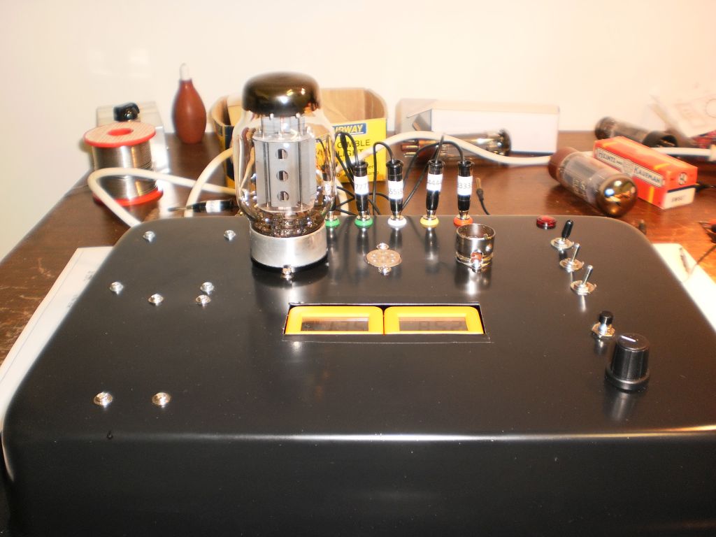
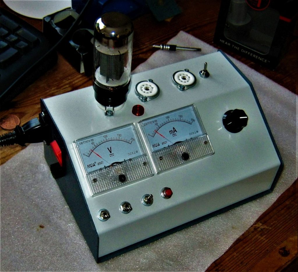
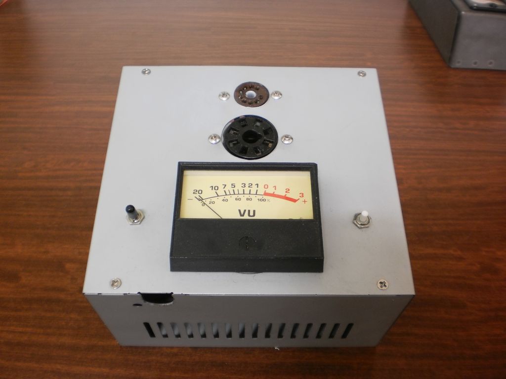
Here is the finished tester constructed in an old computer power supply case:

OLYMPUS DIGITAL CAMERA

This tester provides a basic “emission” test – provides an indication of the capacity of the valve’s cathode to emit electrons. In  much the same way that car tyres wear and eventually need replacing, a valve’s cathode eventually loses the capacity to emit electrons and the valve is “tired”. This tester provides an easy way to assess the condition of a valve – great for checking power valves that have seen a bit of life. It won’t allow for matching valves – you need a more comprehensive tester like my earlier unit to do this.

However, this simpler tester is ideal for a quick comparative test of the condition of your power valves. It works by applying a raw AC voltage between the cathode of the valve and the control grid which acts as an anode. The current that flows is measured by a moving coil meter and this indicates the condition of the valve. The amount of current is dependent on the valve type, however a comparison can be made with a known good valve to ascertain the condition of the valve that needs to be tested.

Here is the schematic of the tester – click on it for a larger image.

Power valve tester

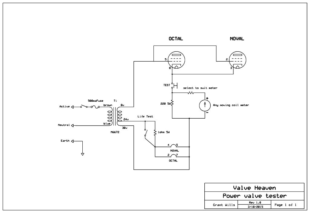
You can see how simple the tester works out to be in practice. A commonly available M6672 30V 1A transformer supplies the heater of the valve under test with 6V and the full 30V is applied to the grid of the valve which acts as the anode. The M6672 does not have a 6V tap, but by changing the arrangement of the transformer the 30V becomes 0V, the 24V tap becomes 6V and the 0V becomes 30V.  For those in other countries, two transformers could be used – a 6V transformer for the heater and a 30V transformer for the higher voltage. A 220 ohm 5W resistor between the cathode and the other end of the 30V supply completes the test circuit. The valve effectively rectifies the applied ac voltage and develops a voltage across the 220 ohm resistor which is proportional to the current that flows through the valve.

A moving coil meter wired as a voltmeter with its series multiplier resistor measures this rectified voltage and provides a direct reading of the emission of the valve.  Conveniently, the grid and cathode pins are common to a host of power valves, which eliminates the need for the switching which is normally needed in a valve tester.

One very useful feature of this tester is the “life test”. The life test switches a 1 ohm 5W resistor in series with the valve heater to reduce the voltage applied to the heater by about 1 volt. A valve that is low in emission can sometimes measure ok, but when the life test is switched in will show a significant drop in emission. A good valve will still read a good amount of emission even when its heater is underpowered by a volt.

A note about the analog meter – an analog meter is preferred to a digital meter as it is easier to see the reading on a dedicated analog meter scale rather than having to remember numbers on a digital meter.You get an intuitive feel for how much meter deflection you expect to see with a particular valve. Just about any meter can be used from a 50uA to a 1mA movement. New meters are available cheaply from Jaycar and Altronics. You may be able to scrounge an old VU meter from a radiogram or tape recorder.

To use the meter of your choice, you just need to select a suitable multiplier resistor in series with the meter to read about 80% of full scale with a good valve being tested. I suggest you start with a 47K resistor and keep reducing the value of the resistor until you read the 80% of FSD with a known good valve. I used an old VU meter with the internal rectifiers and multiplier removed. This unit had a FSD of 80uA and the series resistor was around 22K.

I used an old computer power supply case for the prototype, alternatively the tester could be built into the largest plastic “Jiffy” box from the usual stores.

A very useful tester and easy to build as well!

Cheers!

Restoring an old 1956 AVO meter

In addition to my passion for valve technology, a close second interest is Test Equipment. Over the years I have developed and built numbers of oscilloscopes, signal generators, valve testers, power supplies and many test meters designed to test a range of electronic components.

I was therefore excited recently to be given an old AVO multimeter made in England in January 1956. AVO meters have a long history going back to 1923 when the original designer came up with a design to combine an Ammeter, Voltmeter and Ohmmeter in one unit – the “AVO”. They have been regarded as the “Rolls-Royce” of multimeters and until recently I had never owned or used one in the flesh. They are built like a tank and have a precision unlike most analog meters – within 1% on DC ranges.

OLYMPUS DIGITAL CAMERA

This particular AVO was a model 7 mkII version with the code A156 marked on the meter scale indicating it was made in January 1956. It was in particularly poor condition when it was given to me. Several of the DC and AC voltage ranges were not working, and the meter movement was sticking and was reading low. To start the restoration, I spent some time cleaning the very dirty front panel and case with a toothbrush and mild detergent. After several applications of this treatment, the 60 year old grime was removed revealing the original  black bakelite front panel.

OLYMPUS DIGITAL CAMERA

I then set to work on the mechanical and electrical issues with the AVO. First I wanted to know why the voltage ranges were not working. The different ranges in a voltmeter are arranged by adding series resistance to the meter movement – called multiplier resistors. My guess was that one of these multiplier resistors  was open circuit and so it turned out to be. avo_7_analogue_avometer_sch

On the lower left of the circuit you can see the multiplier resistors in series. The 4500 ohm resistor was open circuit. These resistors are precision wirewound to a tolerance of .3% and hand made. I attempted to repair the resistor but it was broken internally, so I wired in place a parallel combination of 2 resistors selected for exactly 4.5K ohm.

OLYMPUS DIGITAL CAMERA

Having repaired the multiplier, all ranges were checked and found working. However, the meter was reading low and was sticking at about 2/3 deflection. Taking extra care, I removed the meter movement. It is a substantial affair with large alnico magnets. Sticking in a meter is often due to very small magnetic filings lodged in the gap between the movement coil and the meter magnet. Carefully I found some particles and removed them which freed the movement. A small adjustment to the meter magnetic shunt completed the repair.

OLYMPUS DIGITAL CAMERA

The AVO was now restored to full working condition. While its performance can be matched with cheap digital multimeters these days, it was a lot of fun restoring it and maybe my amp designs will have a bit more mojo and vintage tone if the AVO is used in developing them 🙂

A low cost, easy to build diy valve/tube tester

***My valve tester prototype is up for sale for A$300 plus postage. Only available to Australia. To purchase, contact me at my email address. First in, best dressed!!***

For quite some time I have been looking at developing a design for a diy valve/tube tester that is easy to build and uses readily available, low cost parts. A valve tester is an invaluable tool for those who wish to build and repair valve amplifiers.

Old vintage valve testers are available online, but most of them provide only a crude “go/no-go” result. They also fetch ridiculous prices for such simple tests. What is really needed is a tester that will measure a valve at true operating conditions.

In looking at a new valve tester design, I wanted it to provide these features:

1. Provide emission readings at the recommended databook operating conditions (Plate, Screen and Grid voltages)
2. Provide Gm or mutual conductance readings, directly or indirectly
3. Test valves for internal shorts
4. Test for “gassy” valves – valves whose internal vacuum has been compromised
5. Test a wide range of valves, from 12AX7s to KT88s and any other “receiving” class of valve
6. Be expandable with options to include heater/cathode leakage testing, other valve bases, different heater voltages, “life test” etc

I have recently completed the following tester design which does a great job of testing any valve/tube in the “receiving” class. Unlike the old “emission” testers of the past, this low cost tester provides a true test of a valve at valve databook conditions. In addition, it tests for shorts and “gassy” valves with the ability to measure the Gm or transconductance of a valve. It uses low cost, readily available parts and can be built for well under A$100.

Full design and constructional details can be downloaded by clicking on this link:

An inexpensive, easy to build diy valve tester

Here is the completed unit testing a KT88 valve:

OLYMPUS DIGITAL CAMERA

8/5/2019 Some photos of another finished tester from Rob in the UK

And another successful build from Johan:

And another build by Chang

And another build by Robin from the Netherlands
The internals of Robin’s tester
And another recent build by Lars!