I regularly receive emails with questions about a Hi-Fi valve amplifier design I developed many years ago. The design has been posted on a few websites and I thought it would be a good idea to re-post it here and to add some updated information.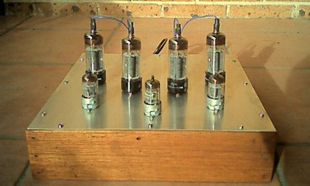
Here is the schematic for the amplifier – click on it for full size.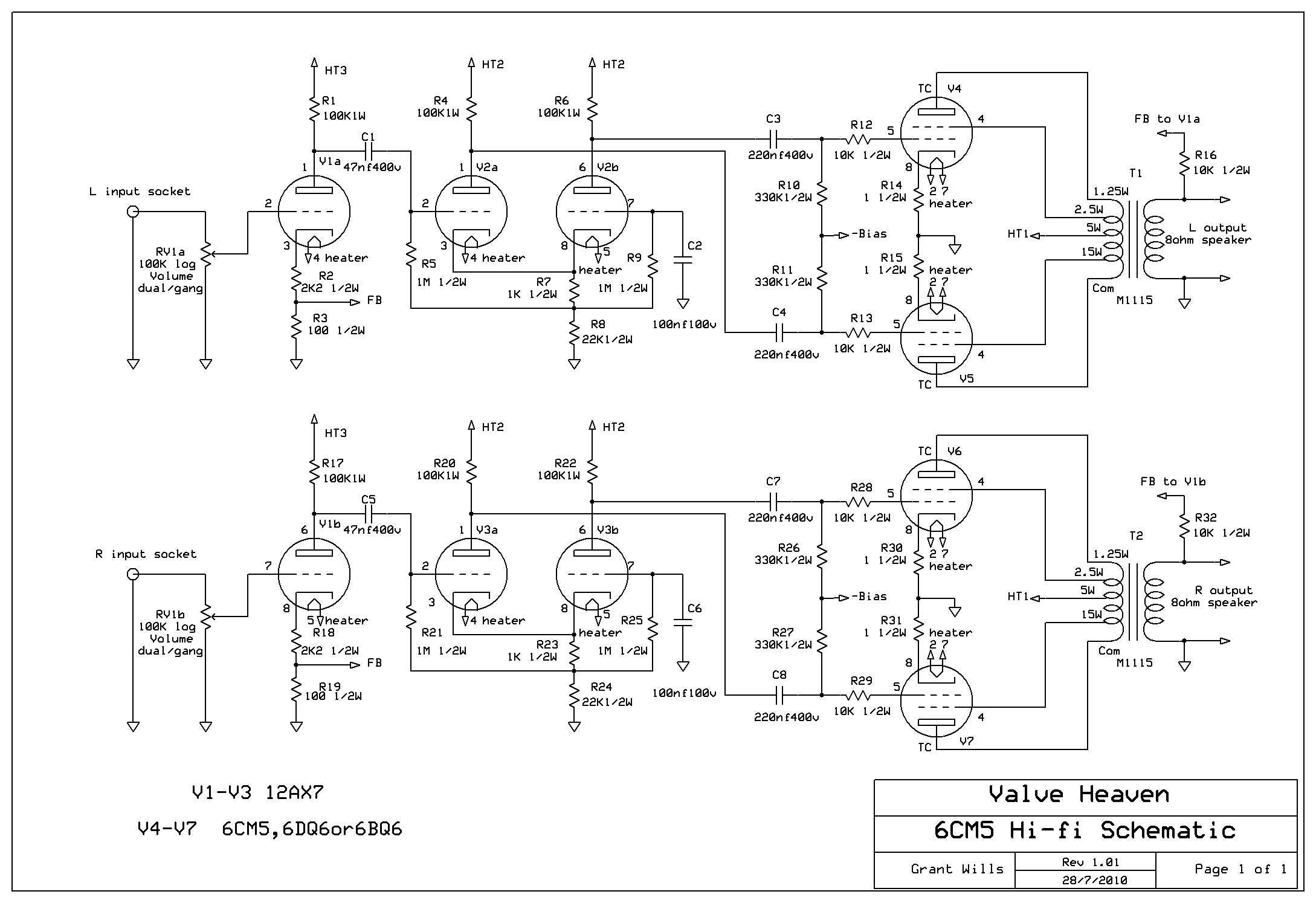
And here is the text that accompanied the original design:
“This is a design for my 15W/channel ultralinear hi-fi stereo amplifier. The front end of the circuit is conventional. The Mullard 5-10 amplifier uses the same phase splitter as I have, and the text refers to it as “a cathode-coupled phase splitter”. The output stage initially used 6L6 valves with a supply of 300V as again I had some on hand, but after quite a bit of experimentation with other output valves I landed on 6CM5 valves.
As is well known, they are an odd valve to be used for audio applications, and I had several unsuccessful attempts to use them. I thought initially that I’d feed the screens with 1/2 B+ as that is how data sheets suggest you should do (and incidentally how similar line output valves such as 6DQ6 are configured in old guitar amplifiers). However, any attempt to use them in this way caused fairly violent oscillation at ultrasonic frequencies. In addition, I wanted to use them in ultralinear configuration and tying the screens at 1/2 supply did not permit this. The ratings indicate a maximum screen supply of 200v and so I hesitated to use the ultralinear mode. However, after trying several configurations which either oscillated, distorted or otherwise misbehaved, I tried them in ultralinear mode with a fairly high amount of bias (-50v), and they worked really well. They were by far the most linear of any valve I tried and worked well with a fairly low standing current (approx 25ma each) and put out the maximum power (17w). This seemed to justify their rather high heater power requirement. So it seems that it is fine to run these valves with higher screen voltages.
The power supply used an old Philips valve power transformer which was up to the fairly high heater current load (4x 1.25A + 3x .3A = 5.9A) and had a ht winding of 110v which applied to a voltage doubler provided 300v HT. I decided to use fixed bias as it allows higher plate to cathode voltage for the output valves than cathode bias. The technique of getting a negative bias voltage from a voltage doubler is an old trick from guitar amplifier designs. I added a 10 ohm resistor in each 6CM5 cathode earth return to monitor cathode current and act as a fuse under overload conditions. Note that the circuit doesn’t have any provision for individual adjustment of output valve standing currents. This was because I used 4 Radiotron 6CM5’s from the same batch with very similar characteristics. A couple of other 6CM5’s that I tried varied a bit in standing current. It may be helpful to modify the bias supply with 4 x 50K trimpots in parallel and then in series with an 82kOhm resistor to ground across the bias supply in place of the one 100kOhm trimpot. With each trimpot wiper independently feeding each output valve this arrangement could then provide individual bias control over each valve. If the bias voltage needs to be increased, the value of the 220nF capacitor feeding the bias rectifier can be increased.
Construction was fairly easy as I took a leaf out of many current hi-fi amp designs. I simply made up a square plinth of timber which has a 12 by 12 inch aluminium sheet (from Dick Smith or Jaycar) fixed to the top. Easy to make and it makes a great furniture piece. I checked the frequency response figures – the amp has a wide frequency response with sustained bass and sounded very nice indeed – even my wife immediately noticed a dramatic difference in sound to our existing solid-state hi-fi amplifier. The S/N ratio for this amp was outstanding – maybe the C-core power transformer, or the star earthing, or the provision of a centre-tap on the heater winding, or my 100µF overkill filter capacitors on the small signal HT? The noise and hum are just about inaudible listening directly to the drivers of my quite sensitive speakers – certainly better than other amplifiers I have used over the years, and pretty amazing for a valve amp! Overall, a lot of fun to build, and a most satisfactory result.“
Here is an underside image of the original design: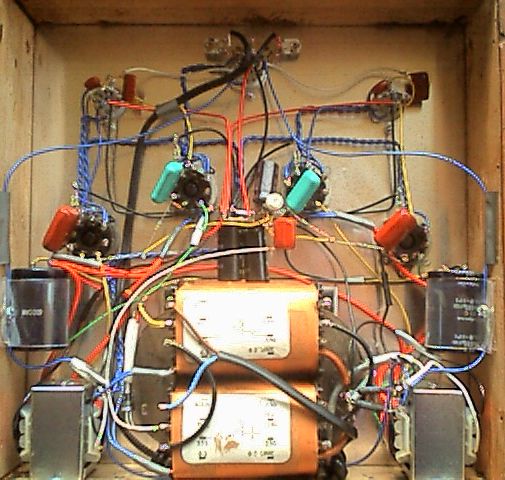
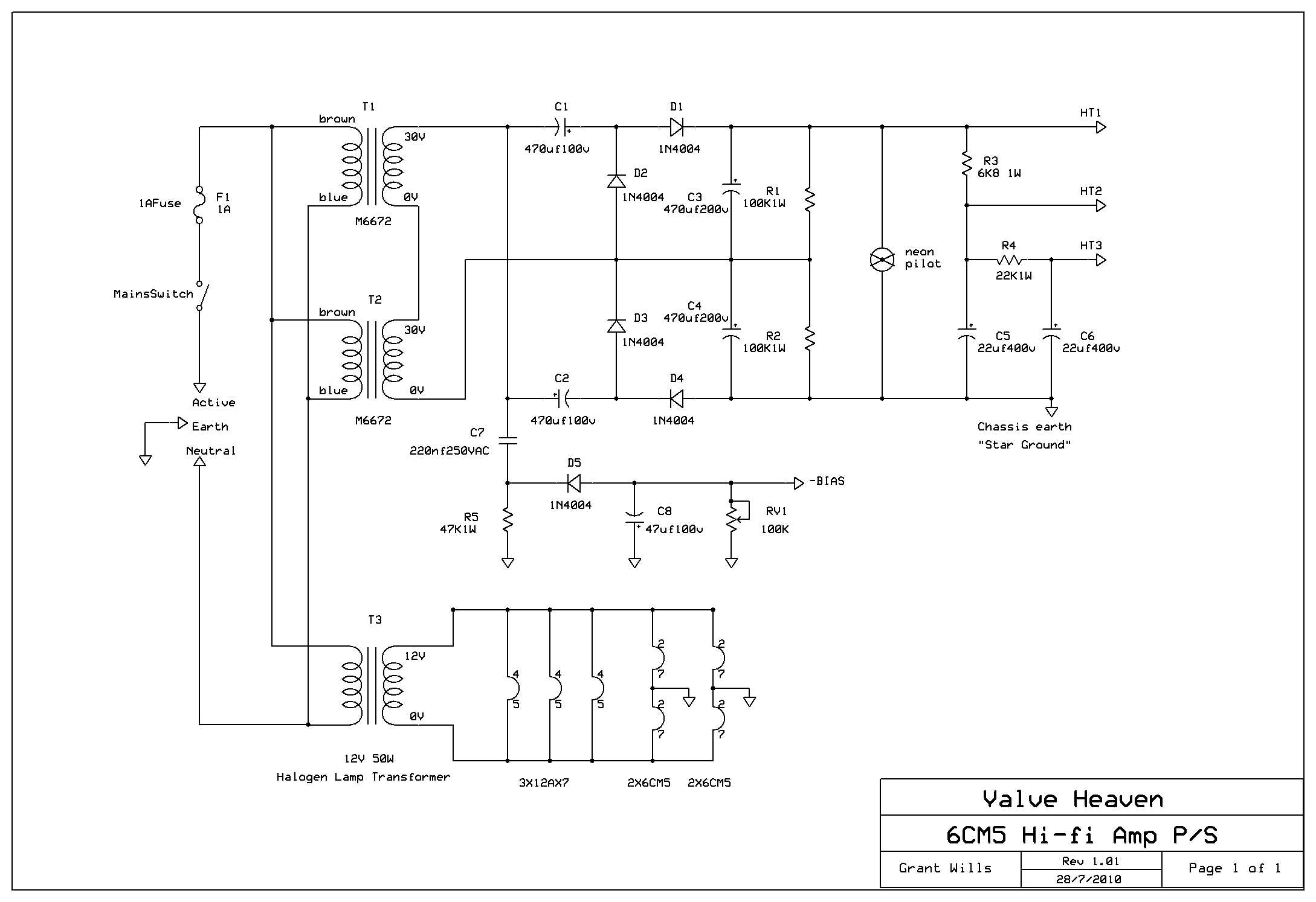
Since I developed this amplifier, I have received many requests for an alternative power supply for the amp. The original used an old TV power transformer which is not available any more and so I looked at an alternative power supply using similar voltage multipliers to my Lamington designs. Here is a schematic for an updated version of the power supply adapted to use currently available transformers here in Australia. Click on it for full size.