
For quite some time I have been looking at developing a design for a diy valve/tube tester that is easy to build and uses readily available, low cost parts. A valve tester is an invaluable tool for those who wish to build and repair valve amplifiers.
Old vintage valve testers are available online, but most of them provide only a crude “go/no-go” result. They also fetch ridiculous prices for such simple tests. What is really needed is a tester that will measure a valve at true operating conditions.
In looking at a new valve tester design, I wanted it to provide these features:
1. Provide emission readings at the recommended databook operating conditions (Plate, Screen and Grid voltages)
2. Provide Gm or mutual conductance readings, directly or indirectly
3. Test valves for internal shorts
4. Test for “gassy” valves – valves whose internal vacuum has been compromised
5. Test a wide range of valves, from 12AX7s to KT88s and any other “receiving” class of valve
6. Be expandable with options to include heater/cathode leakage testing, other valve bases, different heater voltages, “life test” etc
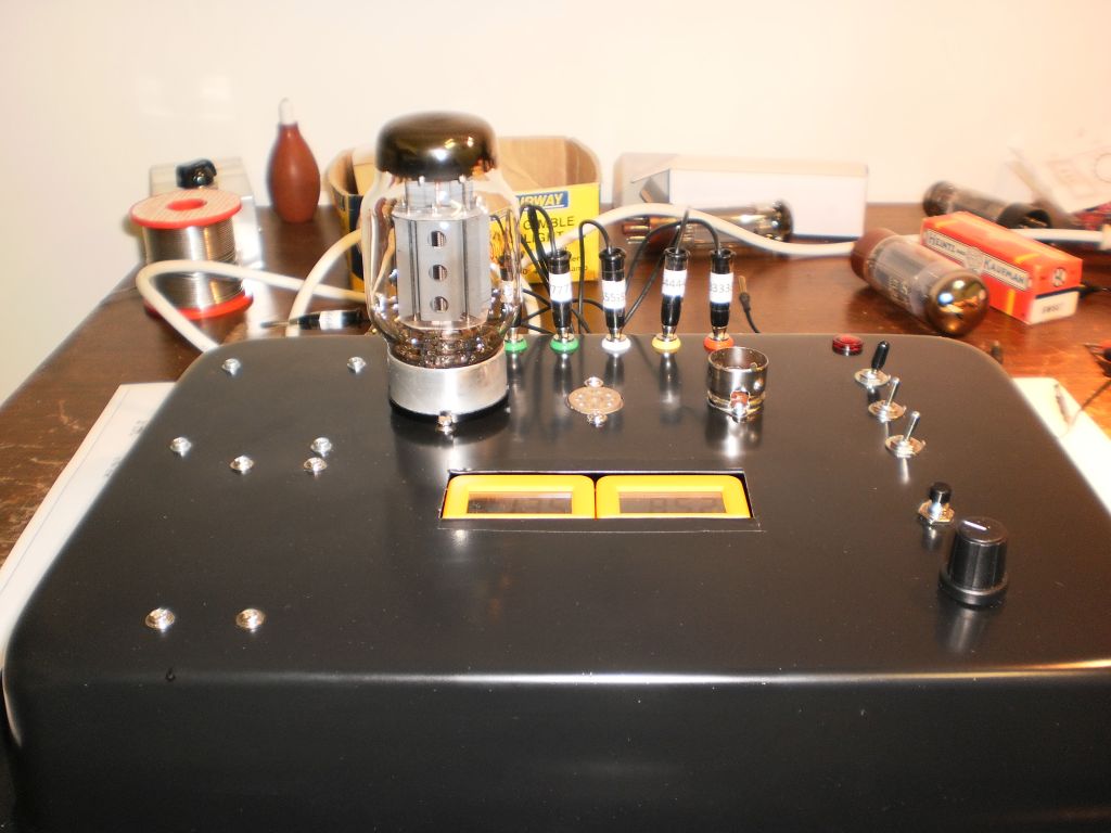
I have recently completed the following tester design which does a great job of testing any valve/tube in the “receiving” class. Unlike the old “emission” testers of the past, this low cost tester provides a true test of a valve at valve databook conditions. In addition, it tests for shorts and “gassy” valves with the ability to measure the Gm or transconductance of a valve. It uses low cost, readily available parts and can be built for well under A$100.
Full design and constructional details can be downloaded by clicking on this link:
An inexpensive, easy to build diy valve tester
Here is the completed unit testing a KT88 valve:
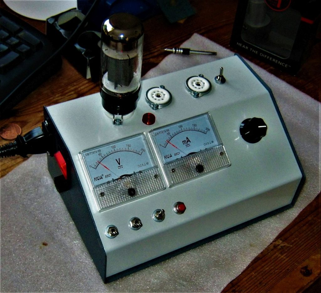
8/5/2019 Some photos of another finished tester from Rob in the UK
And another successful build from Johan:
And another build by Chang

And another build by Robin from the Netherlands

The internals of Robin’s tester

A recent build by Lars
And a recent build by Adrian Langford
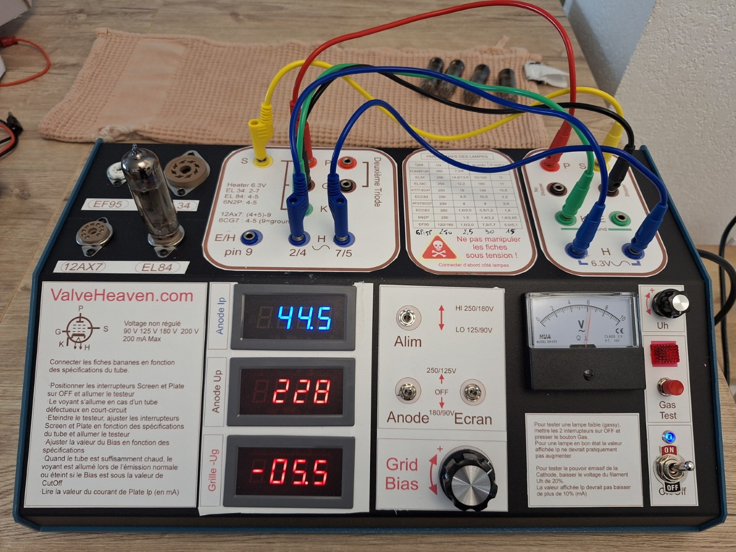
A recent build by Patrick from France

Hi Grant I am looking to build this project and after looking at your PDF instructions seem to be a bit confused with the back of the power board wiring.. There seems to be 3 resistors that are located on the board but not listed on the schematic or have I miss read something here. Thanks for the post of this tester and hope to complete soon…
Thanks Wayne for your interest in my valve tester design. Yes, the photo of the prototype power board shows 3 bleeder resistors, but the single 150K resistor as shown in the schematic will do the job fine!
Hi Grant I have started the build on the valve tester. Just trying to clarify the use of the DPDT TOGGLE switch listed in your build shopping list. From the photos of the build it looks as though this switch has been used to tap the two HI/LO taps from the transformer and also an additional supply to the bias supply via D2. Would this be correct? Adding further to this, is the DPDT switch be bridged across each pole to effectively use as a bigger SPST switch. Just trying to work out what looks to be solder on those lugs from your supplied photos. Thanks once again.
Hi Wayne,
Great to hear you are progressing with your build. Yes, I wired both sections of the DPDT switch in parallel to increase its current rating.
The bias supply is permanently wired across the full 30V winding.
Cheers!
HI there 🙂 I am interested in building this handy tube tester of yours but I am a little confuse with the switch in the picture and in the schematic,In the full version of your schematic it looks like the Screen voltage and Plate voltage are using DPDT switch and the HI /LO switch is a SPDT correct?. In the picture it looks like you have either 2 HI/ LO SPDT or an independent Screen and Plate voltage control. Would you kindly guide me through? 😀 I’m 16 and I have a passion for tube amps 😀
Hi Ben,
Thanks for your enquiry.
The plate and screen switches are SPDT centre off switches. The hi/lo switch is a SPDT switch. In the prototype I used a DPDT switch wired with both sections in parallel.
Hope this helps and all the best with your interest in valves!
Hey Grant.
Very awesome project. Ordered my parts. Had to change a few things here and there, only because South African Electronics stores don’t always carry the stuff I need – only separate transformers for supply and heaters. What I actually wanted to ask is I see there is a resistor next to the Neon lamp on the schematic with no designator or value. Is it needed?
Regards
Hi Nicholas, great to hear you are building my tester. The neon is shown with a series resistor as a complete 240V neon assembly. When you purchase a 240V neon “lamp” it has the resistor built in. Of course if you are using just a neon bulb, you need to add a resistor of approx 220K in series. Hope that helps!
Interesting project.
In my ´transformer bin´ I have an old PT110. Primary 230V secondary 6V3 and some 265V. Please help me how to convert the secondary 265VAC to the required voltages 90/125/180/250VDC. A simple transistor in a resistance divider would not suffice I think because of the high CE voltages involved. But maybe you have a simple solution?
Hi Arjen,
Thanks for your interest in my valve tester project. Unfortunately a standard high voltage transformer does not allow for the different voltages required for a tester. My tester which uses a low cost low voltage transformer and voltage multipliers provides the voltages required with easily sourced parts. Cheers.
Hi Grant. First thanks for making available such a great design. Will build this probably on a PCB as I will use a smaller enclosure. You say other tube sockets can be used of the receiver type. Could you explain a bit more. I never use 7 pin but lots of the other two and 300B, 2A3. Can this be done? With probably more grunt in the PSU particularly for the 2.5V 2A3’s.
regards Dave
Hi Dave,
Great to hear from you. My tester was developed for indirectly heated valves and could be expanded with say UX4, UX5, UX7, loctal, etc sockets depending on the type of valves being tested. As it stands, it was not developed with directly heated valves like 2A3 and 300B in mind, but in theory the tester could be adapted by using different taps on the M6674 to provide the different heater voltage for these valves. If you have success modding the design for directly heated valves, let us know!
Thanks Grant,
1. Had a look and a big think. Simplest way to add most 4 pin DHT tubes to your design is to just suck it in and buy another transformer. The Hammond 266M5 will do but VT4C has one at USD15 +post much cheaper.
2. For the displays I understand cost was the design mantra. I will use 2 DC DC isolated converters and LCD displays from China – 20ma each no big design deal. The DC converters are about the price of two good batteries. And must admit I hate batteries as they seem to die just when you need them.
3. Just another point of view I guess which I hope helps.
4. As would getting this Project to the PCB stage. Used to make my own PCB’s but now firms in China deliver a quality product cheaper than I can do. And they deliver 5 boards as the minimum order for less cost to build my one..
5. So Grant gets a freebie of course. I already have 2 more interested. With Grant’s OK anyone else interested ?
regards Dave
Thanks Dave for your thoughts. Would be great to see the design expanded to test DHTs. Keep us posted on your build!
Hi Dave,
If you still have the PCB available, I would be very interested. Happy to pay postage etc. Regards John.
Did you ever finish the PCB? I’m interested in something that will test Direct Heated Triodes. I work on old jukeboxes that use 30’s and 45’s . I also use 300B’s. Old tube testers are going for ridiculous money. I’d rather build something I can get parts for.
Hi Dave, I am interested.
Hello, very nice your tube tester.-
I want to, but I have to ask you a question:
Banana sockets : 7
P : Plate (anode)
S: Screen (g2)
G: Grid (g1)
H: heater
H: heater
K: cathode (k)
E: ??????? —– For what electrode is?
I await your response
Thanks
Best regards
Hi Gus,
Great to hear you are planning to build my tester.
To explain, the E socket is wired to ground and is useful for testing certain valves. For example, for connecting grid 3 of an EL34 to ground, or for supplying heater power to a 12AX7 by connecting pin 4 of a 12AX7 to “E” ground so that pin 5 can be grounded to heater ground and pin 9 connected to heater 6.3V.
Hope this helps!
Grant
Grant, thank´s for answer.-
Another question:
In the part list : D1-D4, D11 are 1N4007, but in the circuit diagram D11 is 1N5404, so wich is right ?
I await your response
Best Regards
Gus
Hi Gus,
Yes the circuit shows D11 as a 1N5404 but you can use 1N4007 also.
Cheers
Hi Grant.
Share your love of valves so as said earlier here now working on a version to include the valves I use. Yup I know very selfish but let’s face it. Why build something you don’t use. Your great design as the basis pretty much intact. Would have taken a while.
Don’t know how to post layouts here. If there is a way will share.
regards
Dave
Nice project… I’ve managed to source most of the parts, but I’m in the US which makes the transformer a bit of a puzzle. I could conceivably use a clothes dryer outlet to power the 240v transformer, but the M6674 doesn’t seem to be available in the states and shipping one here drives the cost up quite a bit. Far better would be a transformer with a 120v primary, but I’m just not having any luck finding a suitable substitute… just curious if anyone else has had any luck finding the right transformer.
Hi, great to hear of your plans. Re a power transformer for the USA, you can substitute the M6674 with two transformers – one 120V to 6V 2A and the other 120V to 30V 2A centre-tapped (ie 15V-0-15V). Both are available from ebay or Mouser etc. Happy building!
Hi Grant,
I’d love to build this tester. I’m in the USA. Can you go into a little more detail on how you would change the schematic for the two transformers (120V to 6V, and 120V to 30V) you suggested?
Hi John, I’ve posted some details earlier in this thread. Cheers.
Yeah, that was what I was thinking, but I wasn’t sure what amp capacity I would need.
I think I will dispense with the opticoupler part of the circuit. Instead I think I’ll build the tester inside a suitcase type of box with room to store a pair of bias probes and a pair of multi-meters that do double duty. I can just grab the kit to match tubes and bias an amp.
Hi Grant,
I’m looking to build the tester and looking at a solution for the heater supplies. Will it be possible to draw the heater supply from the top half of the 15V AC winding? (assuming the bottom end of the winding is grounded). I am looking at using at 30VAC center tap transformer of 80VA rating? Am planning to use a regulated DC for the heaters either via 78xx or LM317. Appreciate your input. TIA..
Hi David,
Great to hear of your plans for the valve tester. Re using a 15-0-15 transformer and supplying the heater from the 15V winding, it could be done, but is very wasteful of power and would result in large dissipation (read heat!) in any dropping regulator etc. For example, if you were testing an EL34 with its 1.5A heater requirement, the regulator would be dissipating around 18W of power with attendant heat problems. I’d suggest that you chase up a separate 6V 2A transformer – simpler and easier to wire up and no heat issues.
Hi Grant,
Thank you for your response. In other words what you are suggesting is just going for an AC heater supply instead of DC regulated supply. In order for me to test valves having 12.6V filaments, i would need to get a dual secondary 6V transformer. The problem i am facing where i am is the AC supply is about 240-245VAC. Transformers i am able to purchase are 230VAC. Usually there’s a 20% increase on the supply on the secondary windings. I would need to get the supply adjusted down to either 6.3 or 12.6. Using a series resistor to drop the voltage down is one way, but wouldn’t this vary for different valve filaments? Do you have a better way of implementing this?
thanks,
David
Hi David,
Re your concern about mains voltage variation, I wouldn’t be too concerned about it. As long as the heater voltage is within say 15%, you should be fine.
Cheers.
Thanks Grant…Cheers
Hi Grant,
Great DIY project just what I need. I am having difficultly in locating a transformer M6674 some searches come back with M6674 L I live in the UK and this transformer does no show up here. Tried a search for a 240v/30v 2a center tapped transformer but cannot find this type in the UK either any thoughts would be great as I would really like to build the tester.
Thanks
Dave
Hi Dave,
There are several ways to provide the AC voltages required for the tester. I suggest looking for two 240V to 15V 2A transformers if you can’t find a 30V 2A. Ebay is your friend here 🙂
Hi Grant,
I located 240v/30v 2a center tapped transformer. You mentioned getting a 6V 2A transformer for the heater supply. How is this used as in the schematic this taken from the 24v tap of the M6674. Not sure how that comes out at 6.3 volts.
Thanks
Dave
Hi David, just connect one side of the 6V winding to the bottom of the 30V winding as per my schematic and connect the other side of the 6V winding to the heaters. Cheers
Hi Grant,
a couple of quick questions: The M6674 transformer seems to be discontinued at Altronics. Jaycar have the MM2005 30V 2A multi tap transformer, with 15v as the centre tap. Can you suggest if this is a suitable replacement? And secondly, having trouble sourcing 470uf 350v caps…any ideas here? Thanks.
Hi John,
Yes, the MM2005 is an equivalent of the M6674 so is interchangeable. 470uf 350V caps are available from Altronics in Australia. Cheers!
Hi Grant,
Planning to build the tester but can’t find the 470uf 350v caps anywhere. Jaycar haven’t got them and I can’t find them online.
Any pointers?
Cheers
Rohan
Hi Rohan,
470uf 450V capas are available from Altronics. Cheers.
Hi Grant,
I’m also planning to build this valve tester, have gathered most of the parts except the capacitors. I did have some questions but reading through the previous posts they have been answered!
Thanks for your work.
Cheers Keith.
Great Keith!
Hi Grant, first off I would like to say that your plans have been very helpful in helping me understand how to test tubes.
I have been working through your schematic to understand how it works before I just start throwing parts together. I plan on building the MKII with the banana plugs and such. So far I understand why your are using the seven banana sockets and understand that P = plate, S = Screen, G = Grid, etc but the only one I don’t get is the E = ?. Could you please explain to me a little further as to where and/or how that would be used? I was comparing both schematics for the MKI and MKII but I’m lost as to what the E would be used for in the second design. If it’s one of those things where it would take to much time to explain, could you please point me in the direction of what I should study? I am just beginning to learn about tubes but I have a strong background in audio and electronics. Any help will be greatly appreciated!!! Thanks.
Hi Richard,
Great – you found the reason for including the E plug.
Happy building!
I probably should have read through all the comments first because that is where you already answered my question…..duh. Anyways you have a GREAT site here, very informative and helpful.
Thanks Richard!
Hi again Grant, this maybe another noob question but here goes. You said in your write up that you could measure Gm indirectly by varying the grid voltage by 1 volt and measure the change in plate current. Could you please explain to me the formula you use to get a Gm measurement in umhos?
Hi Richard, Gm is a measure of the change in plate current for a change in grid voltage. Typically so many mA of change in plate current for a 1V change in grid voltage – mA per volt also referred to as milli-mhos. To convert to umhos (micromhos) just multiply this figure by 1000.
Hope this helps! Grant
Thanks Grant!!! That helps quite a bit…I was wondering how everybody was getting such large figures. Thanks to you and several other online resources, I believe that now I’m finally getting a grasp on how it all works: tubes, amps, testers, etc.
I think I am going to use your basic design and try to incorporate that into an Arduino with a 16×2 Lcd. I know I will be able to get it to measure the grid volts properly but getting the proper resolution for the mA might prove to be beyond the abilities of the standard Arduino (I’m trying to be cheap and not buy anymore extra parts 🙂
Anyway thanks again for you help and all the info!!!!
Hi Grant, thanks for publishing your design for such a fantastic basic tube tester. My audio system uses tubes in all amplifiers, and the DAC output, and my Monos are OTL’s which have 16 output tubes each,…so being able to test and match tubes is paramount for me. A simple query if I may, have looked at the readings for the 3 tubes you tested and published, 6V6, KT88 and a 12AX7. I whipped out my performance sheets for the 12AX7 (RCA) and your result matchs fairly well with RCA’s data using a Plate V of 250V, and indicates that triode half is good as new. But the KT88,….well I then pulled a performance sheet from Svetlana and their sheet has data for “Vscreen of 300V”, “Vscreen of 140V”, “Triode Connection”, and finally “UltraLinear Connection”. OK, so I’m guessing that I should be referring to one of the first 2 graphs, but the tester cannot supply Vscreen voltages for either. Could you please help me apply your results to a know KT88 graph so I can then interpret my own results against other tube graphs when I start testing tubes with this tester, I’m about half way thru my build. Cheers, Mark.
Hi Mark,
Thanks for your kind comments and background to your build.
Re the KT88 or any other valve, I would suggest you do some web searching for several datasheets. I found this Genalex datasheet at National Valve Museum http://www.r-type.org/pdfs/kt88.pdf and it refers to tetrode data of 250V anode and screen which suit the voltages available from my tester.
Cheers, Grant
Grant, really nice concept and design, it’s not easy making something that works AND simple!!!
That being said, I’m a Yank, and that tranny won’t work easily for us… What do you suggest, a 30V CT and a 6.3v heater tranny’s?
A quick look through ebay, and I saw some dual display panel meters, DC Volt/Amp… Not sure of teh range, but that might be teh ticket…
CR
Hi Chris,
Good to hear from you.
Yes, numbers of my tester have been built in the US with substituted power transformers. You can find them on ebay or Mouser – you need a 120V to 6V 2A and a 120V to 30V centretapped at 2A.
The ebay panel meters could be used, but be aware of how they reference the ground – ie the common input will be typically tied to the power leads. If they are used, you will need to power them from an isolated power source. That is why I used isolated DMMs for the meters in the prototype.
Have fun!
Hi Grant,
Love your project so much that I have already printed a dozen copies of the pfd. Still, I ask myself, how does your baby compares to the sussex tube tester?
Cheers,
David
Hi David, thanks for your comments. Re my tester vs the Sussex tester, my design is quite a lot simpler. The Sussex tester allows you to select a wide range of plate and screen voltages, while mine simplifies this to a lower number of test voltages that are those commonly used in valve data sheets. This simplifies the power supply considerably, while still providing usable measurements at data sheet settings. Cheers!
I greatly appreciate your circuit since it is most necessary for the tube guru on a budget.
However, I have a question that I hope you can resolve.
Viewing the basic schematic, four toggle type switches are present as noted below:
Hi/Lo on the sec of the xfmr (SPDT)
Screen Volts (SPDT)
Plate Volts (SPDT)
12AX7 sec1 & sec2 (SPDT)
Why does your pictures and parts list show a DPDT switch, is only 1 section used?
In the event the latter is the case, can I use another SPDT to replace the DPDT.
Please identify/clarify where the switches are regarding the schematic in reference to the pics.
The above is not written out of any disrespect, I am puzzled…
Thank you!
Sorry, for my previous question – I noted the info within the thread.
Thank you for the excellent circuit, it is very thoughtful of you to present this circuit to us.
I have noticed a few testers that have an audio IN/OUT RCA phono jack for actually listening to the amplification through the preamp tube test; would it be possible to place a circuit in your project to provide the latter?
Hi Frank,
Thank you for your encouragement and good to hear you found your answer in the previous comments.
Re using the tester to check for noise and sound, I haven’t done this but in theory it would be possible. You would need to inject audio into the grid and put a transformer in the plate lead to couple audio out.
Cheers!
Hi Grant.
Beautiful project especially for the availability of the components used.
I’m trying to make it happen and in the meantime I have collected almost all the parts except for the transformer I’m doing … and built specifically to test other valves 2a3 and 300B kind I added another processor only for these tensions ….
tThe My question is this ….. starting to assemble pending the transformer, I did not understand at best, even reading it tread, connecting 2 spdt and dpdt, it would be possible for her to post a more detailed picture of the various connections or mark with “s1”, “s2” etc .. the location of the switches in the wiring diagram ??
Thank you
Tony
Hi Tony,
Great to hear you are building my valve tester. Re the switches, I used a double pole switch for the HI/LO function with both sections in parallel. The other two switches are single pole.
I’m interested to buil this tester thats seems very simple but i’m in doubt about DVM’s conectiion.
I didn’t understand the connection of batteries Could you be a little bit more clear about? If possible send a photo showing the conncetions.
Tks
Hi Paulo, good to hear you are planning to build the tester.
Re battery connections, just disconnect the positive battery lead and wire it to the opto isolator as shown in the schematic. The other side of the opto connects to the lead you have removed from the positive terminal.
Hi Grant,
I’m planning to build the realy nice tester you’ve developped. I’ve one question about the banana sockets. In the schematic I see 7 banana sockets, but on the pictures of the tester I see only 6 banana sockets. Why is that?
Greetings,
Adrie
Hi Adrie, the extra terminal is used for a valve needing an extra ground like a suppressor grid, or a twin triode needing a different heater arrangement. In my prototype, I added the extra ground banana socket at the rear of the chassis to make a total of 7 sockets. Regards, Grant
hi i came accross your valve tester last week and now have most of it built but ive installed valve bases and rotary switches to ref pins also fitted banana jacks to input higher heater voltages and oddball bases have used seperate trans for heaters to give a wide range of voltages but havent got 15/0/15 trans but have many 18/0/18 ones this gives me 105/145/210/265 after the maltiplier ive not done much with malltiplier circuits can it be altered to acheve different set of voltages?thanks phill
Hi Phill, great to hear you are building the valve tester. A 18-0-18 transformer would work in my tester with the proviso that as you say the HT voltages would be increased by 20%. You would need to take that into consideration when testing valves.
can i use a tap off one diode below and use the 87v ? and would i need it , i want to test the valves from a 90 volt battery set with 2 volt heaters , among others , phill
its phill again ref c3 47uf 63v it apears to be upside down is there a reason for this.phill
ok i see its – volt line fotr the grid got it
Hi Grant,
Thanks for this great, long-sought-after (for me) project! It finally puts quality Gm tube testing within my reach. I’ve never been able to afford a quality tube tester.
I’ve looked for the past few hours online, and read through these comments, and I am having a really hard time finding transformer(s) for this project. You mention Mouser or ebay for sourcing an M6674/MM2005 equivalent, as both those are apparently discontinued. I can’t even seem to find 120v to 6v 2a or 120v to 30v 2a center tapped transformers anywhere – most of what I’m finding are the right voltage, but much lower amperage than that. Would you mind looking up some examples on ebay or Mouser and providing me with some actual part numbers for transformers that are actually in stock and not discontinued? It would really help me out a lot. I’m sorry to sound like such a noob with this, but I just cannot seem to locate the key parts for this project and I really want to get going. Thanks again for all you do!!!
Hi Jason, your best bet is to check out Ebay and other online sellers. I assume you are in the US and a quick look on Ebay.com found this: http://www.ebay.com/itm/JAMECO-SHIELDED-POWER-TRANSFORMER-115V-TO-12-6V-center-tap-6-3V-2A-/272229927928?hash=item3f622b0bf8:g:zqwAAOSwFEFXJlgP
And this: http://www.ebay.com/itm/32VCT-32V-16V-Transformer-16V-0-16V-CT-2A-110Vac-220Vac-to-32Vac-16Vac-free-shi-/272031999836?hash=item3f565ee75c:g:TdoAAOSwwbdWM9q1
Grant
Hi, looking to build your tester, BUT not able to get the Transformer in the UK at a fair price, jacar want £28 just for shipping,, could you please tell me if there is any way that i could use the cheepo bench PSU’s that are rated at 30V 5A adjustable voltage cheers and thanks Shawn
Hi Shawn, thanks for your interest in my tester. The 30V supplies that you refer to are DC and not AC and are unsuitable. I suggest you read all of the comments on this project – there are several options that I suggest for builders outside Aust. Cheers!
Hi, one little doubt the transformer its multi secondary transformer , with 30V , 24V, 15V like in the schematic. Thanks
Hi Pedro, yes the power transformer is a multitap transformer. See here: https://www.jaycar.com.au/9-30v-60va-2a-multi-tapped-type-2165-transformer/p/MM2005
Hi Grant
I’m in Trinidad in the Caribbean and currently building your valve tester.
Here are some part numbers and links to the components I’ve sourced for it (115vac 60Hz). Will update the group on the build in due course.
Hope this may help someone.
Cheers, Cletus
Mouser
647-UPT2D471MRD UPT2D471MRD 200volts 470uF
661-EKMQ351N471MA30S EKMQ351VSN471MA30S 470uF 350 Volt
Jameco
29226 TRANS,PWR,12.6VCT/2A,115V/AC, WIRE LEADS
21979 SWITCH,TOG,MIN,DPDT,ON-ON SOLDER,120V/5A,1/4″MTNG.
21952 SWITCH,TOG,MINI,DPDT,ON-OFF-ON 5A@120 &2A@250VAC,1/4″MTG
36011 DIODE,SIL REC,1N4007,1A, 1000V PRV (10)
36265 DIODE,SIL REC,1N5404,3A, 400V PRV (10)
2231961 INDICATOR,NEON PANEL,RED,115V, RNDw/DOMED TOP,4.5″LDS,.50″H
40985 OPTO,4N25,NPN TRANS,2500Viso, 1.2Vf@10mA,30Vb
2246320 POT,LINEAR TAPER,10K,1/8W,20%,16MM,.235″KNURL SFT,PCB TERM
26649 SWITCH,PB,MINI,SPST,ON-(OFF) CHROME,125V/3A,.299″MTG,EYE LUG
120994 FUSEHOLDER,PANEL MOUNT,NON UL .25″X1.25″FUSE,SOLDER TERM 2D
Ebay
https://vod.ebay.com/vod/FetchOrderDetails?itemid=272031999836&transid=1933223240017&ul_noapp=true
Tube Depot
https://tubedepot.com/
8 Pin Octal Socket Drop in Suitable For Fender® Brand Amplifiers
7 Pin Chassis Mount Socket with Solder Tabs
9 Pin Miniature Plastic Chassis Mount Suitable For Fender® Brand Preamps
Hi Cletus, good to hear of your valve tester build and thanks for the links to substitute power transformers and other parts. Cheers.
Oh, and for the meters (I happen to have a bunch of them already here in the shop) :
Amazon
https://www.amazon.com/HOME-DECOR-DT830B-Multimeter-19-Range/dp/B001T3Y8XW/ref=sr_1_fkmr0_2?ie=UTF8&qid=1516153368&sr=8-2-fkmr0&keywords=miyako+dt-830b
Hello folks,
No case made yet, so it’s still in my amplifier chassis jig. But it works sweet!
Here’s my implementation of the instrument:
http://i112.photobucket.com/albums/n197/cberkeley/Tube%20Tester_zpseiggdv9a.jpg
Thanks for a very useful device and a great project!
Hi Grant,
I’m assembling the parts to build your tube tester. I was planning on using a 12vct filament transformer so I can test both 12V and 6V tubes.
Thinking about using a 7809 regulator off the 12V transformer to power the meters. You mentioned they need to have separate power supplies because of different ground pontentials. Can I do what I want by simply using one regulator for each meter?
Hi Jon, good to hear of your plans. You can power the grid bias meter from a ground referenced power source, but the plate current meter floats at HT potential meaning that the power to it needs to be isolated. One builder of my tester took the approach of adding a DPDT toggle switch to turn the meters on and off. You may want to do the same. Cheers, Grant
Good idea!
Thanks!
I would like to build your valve tester but like more of the people who replied to you I have drawn a blank with the transformer.I have got various transformers from old radios but 2 amps.could be a problem. Maybe someone reading this might be able to advise me on a substitute. Regards Dick
Hi Dick, depending on your country there are suitable transformers that can be substituted. What you need to locate are a 6.3V@2A and a 30V@2A centre tapped transformers. Alternatively substitute the 30V centre-tapped transformer with two 15V@2A transformers with the two 15V windings in series. If you look back through the comments above, there are several suggestions for alternative transformers. Trust you locate suitable transformers – it certainly is a useful tester!
Hi Grant,
Thanks for your great design.
Refering to the question of Jon Block, I was wandering if it is possible to take the current measurements from the kathode and not from the plate and getting the same results. Am I right in thinking this and that In this way the mA meter sees no high voltage so a simple ground referenced power supply for a digital meter is possible? Regards, Jaap Schijf
Hi Jaap, the valve current can be monitored from the cathode as you suggest, but this will mean you are measuring the sum of anode and screen currents when you are testing pentodes.
My approach requires monitoring current at a high voltage as you say, but assures an accurate measurement of anode current alone. Of course if you were only measuring triode valves, the cathode current is the same as anode current so your approach would work fine. Hope that helps!
Thanks for your answer. Very helpfull.
Regards, Jaap
Hi Grant,
Thank you for this excellent design! Like others, I had a lot of difficulty sourcing the 30vCT or even 2 15 volt transformers at 2A in the U.S. and finally found one! Here’s the link:
https://www.maddison.ca/adaptateur-transfo/entree-ac-sortie-ac/mad-005787.html
They’re in Canada, and unfortunately do not have shipping to US enabled for web orders, but you can give them a call (if you speak french) or send a google translated email to request a purchase with shipping to US, it’s worth a try, it worked for me. The 30vCT is about $10US and shipping would be about $20US, not the cheapest overall but after searching for any suitable combo of 30vCT or 2 of the 15v at 2A I was just glad to find one somewhere, anywhere!
I just thought I would share since it finally arrived and I’ve confirmed that it has the advertised output.
Hope this helps others that are searching for this elusive part in the U.S.
Thanks again to Grant for the excellent design!
Cheers
Hi Steve,
Thanks very much for the update on sourcing an alternative transformer. Cheers!
For those wishing to use the mini-multimeter Grant sourced from Jaycar (QM1502) they don’t seem to stock them now (2018). Of course, the answer is Ebay. – and I found this item which appears almost identical.
https://www.ebay.com/itm/Mini-LCD-Digital-Voltmeter-Ohm-Multimeter-AC-DC-Voltage-Multi-Tester-Meter/332168009569?hash=item4d56c19761%3Am%3Am30BiVShL9JAprbPH9hl29w&var=541202875604
Thanks Ross for the heads up. Yes, just about any cheap multimeters will work in my tester.
Hi Grant
Just some newbie questions about the ground connections. Are we using the baking tray as the ground plane? I suppose the earth wire of the power cord is also connected to the baking tray, correct?
Cheers
WT
Hi WT, yes the baking tray is earthed for safety. Cheers
Dear Grant, I have sourced almost all part for the valve tester and looking closely at the photo of the power board I noticed that there are two resistors of 220k in parallel; supposedly R7 for the simple version and R5 for the full version. But I also noticed a 100k resistor in parallel with a 470uF 200V capacitor (C7 in the simple version and C6 in the full version). I can’t seem to find the resistor in either schematics, so my question is: Is this resistor necessary?
Hi Willem, great to hear you are building the valve tester. To explain the extra two “bleeder” resistors on the power supply board, they were added early in the build but are not necessary – a single resistor of any value around 150K to 220K is all that is needed. Its purpose is to discharge the power supply capacitors when the unit is turned off. Hope that helps!
Instead of these bleeder resistors can I use and on-off-on power switch with the second “on” switch being “discharge”? “on-off-discharge” for the power switch positions.
Hi Rick, it is not a good idea to short charged electrolytic capacitors as the large discharge current can damage them. Bleeder resistors are a kinder way to discharge a capacitor as the discharge is slower. Cheers
Hi, just how high can you go on the center tappet transformer?
I have some 18-0-18 toroids collecting dust.
Best regards
Hi Rick,
The 18-0-18V transformer would increase your test voltages by 20% – that could be ok if you take it into consideration.
Hi Grant,
I found two transformers on RS Components. May be these are useful for those who are still looking for the transformers.
6.3V dual secondary RS Part No: 504-561
https://docs-apac.rs-online.com/webdocs/15c2/0900766b815c22dd.pdf
15V dual secondary RS Part No: 504-022
https://docs-apac.rs-online.com/webdocs/15c2/0900766b815c22e8.pdf
Just one more question regarding the wiring of the transformers. Does the diagram below look correct? Does it matter if we use 0v lead or the 6.3v lead as the ground for the filament transformer?
https://www.flickr.com/photos/49608673@N02/42069659540/in/dateposted-public/
Thanks again!
WT
Hi and thanks for the link to the RS transformers. They would be viable options for my valve tester. The diagram you linked is fine and it does not matter if you ground a “0V” or “6.3V” lead – those voltages are just relative to each other.
Hello Grant,
I just discovered your design (I’m new to the tube world, but experienced with electronics). I will certainly be building your tester! I have two questions (for now )
1. Neon tube: should it be 240VAC or can I substitute 120 VAC?
2. I would like to use the digital panel meters like this: https://www.ebay.com/itm/DC-200mA-Red-LED-Digital-AMP-Ammeter-Panel-Digit-Current-Meter-0-200mA-DC/110956423447?hash=item19d584a917%3Ag%3AU3MAAOSwOeVZzl-y&_sacat=0&_nkw=Digital+panel+meter+0-200ma&_from=R40&rt=nc&_trksid=m570.l1313&LH_TitleDesc=0
Should I use 0-100mA (to be more accurate?) and voltage Meter 0- 200VAC ? Or 0- 400VAC?
Thank you for making this project.
p.s. I will be testing only the 12AX7, 12AU7, KT88 and possibly 5AR4 (last one is a rectifier tube so I’m not sure if I need a separate tester/configuration).
Thanks again!
Regards,
Paul J
Hi Paul, ideally you should use a 240V neon, but if you have a 110V neon, just add a 220K resistor in series with it.
Regarding the panel meter you suggest, it requires an isolated power supply for each unit and the LED display draws a significant amount of current. That is why I used multimeters that have low current drain and battery supply to isolate them from the high voltage. Cheers.
Thank You for your fast answer – I’m collecting parts now 🙂
Hi Grant,
Thank you so much for the wise design. I love simple and effective designs! it can be easily modified if one wants more features/adaptations.
Cheers.
Aviv from Israel
Hi Grant,
Is there any disadvantage in using a toroidal transformer?
Thanks,
Aviv.
Hi Aviv,
A toroidal transformer or two with the appropriate voltages would be fine for the tester. Cheers.
Hi
Thanks for the project. I was looking at version 1 and only want to use it with 12a*7 tubes. I assume i can eliminate the other sockets and high switches? Anything else i should consider?
Thanks
Hi Jason, thanks for your interest in the valve tester. Yes, the circuit can be simplified if you are only testing 12AX7 type valves. You can also scale down the power supply as it only needs to provide a few mA of current
hello,
how are the DMMs attached to the case? also how are the DMM leads connected or did you solder wire to the sockets?
thanks
I used silicon sealant to fix the DMMs to the case. Yes, I soldered leads directly to the pcb inside the DMM.
brilliant! thx
would adding rcas for signal in and signal out make sense if i wanted to add a freq generator and scope for noise testing?
Hi Jason, in theory this could be done – see my comments above. Cheers.
Hi Grant
Thanks so much, I am based in UK and desperately in need of a valve tester but could not afford one, so this is a gift. I have trawled Q & A’s above but being a newby to more complex electronic projects (sorry if being daft).
Main valves I have to test are 6AS7G – heater pulls 2.5 amps at 6.3 V . So you guessed it Transformer advice AGAIN!!!!! (sorry)
The 2 X RS Tranformers above I assume both are needed (one for heaters one for test supply) making it more pricy? + might be blind but cannot find amp load for them.
I have found this at Jaycar
https://www.jaycar.co.uk/12v-30v-100va-6a-multi-tapped-dual-type-2170-transformer/p/MM2015
Would this be any good? would I have to change anything in your circuit to use it? I tried the Jaycar linked to previously but does not come up!!!
For me this Jaycar if OK would be great as rated at 6 amps and if poss I want to test 6336A/B with heaters at 5amps.
Hi, there might be a few challenges to test low mu triodes like 6AS7 or 6336 with my tester. As you identify, the heater transformer would need to be upgraded for the higher heater current. The other issue is that these triodes need a high value of bias: up to -60 or -70 volts. My tester generates a maximum bias voltage of around -43V and would need to be redesigned to provide the higher amount of bias.
Hi Grant
Thanks for that.
Hmmmm! This might be an issue as 6AS7G is the main valve for me to test. Heaters possibly not so much of an issue as can presuably run a sperate transformer for them. However the bias control? Any idears on how much work to adjust your circuit to accomdate this valves needs? (forget 6336 as I believe even more extreme). Advice on this might help many out there as the 6AS7G is the most common OTL amp valve and they use a lot of them. Here is the data I have on it.
Heaters 6.3 V at 2.5 Amps
–Plate supply 135 Volts
Cathode-bias resistor 250 Ohms
Plate resistance 280 Ohms
plate current 125ma
MAXIMUM RATINGS
Plate voltage 250V max
Plate current 125 mA
Plate dissipation 13 Watts
Peak Heater-cathode voltages Heater neg and Pos with respect to cathode BOTH 300 volts Max
MAX CIRCUIT VALUES
Grid-circuit Res — Cathode— bias operation 1.0 megohm Max. Fixed bias operation NO
Could you also advise on 6SN7GT
Thanks again Grant for your efforts and time for us Valve nutters your passion for valves must be great.
JO
Apologies me again. Trawled through above again to discover nobody seems to of asked so may be I am being incredibly thick but are all the caps polar? non Polar or a mix? If so which are which or does it not matter?
Sorry if ive missed something or being a complete nonse.
JO
ohhh! and thanks again
Hi Jo, yes all of the capacitors except C1 (a 100nf) are polarised electrolytic capacitors.
Hi Grant Ive been studying circuit in an attempt to resolve issues with adding to its capabilities to test 6AS7G. Identified Issues — Heater current, High Bias value and need for higher Voltage supply to plate which I believe is 300V (the 3 issues identified so far, hopefully all of them?)
Separate Transformer to supply Heater part of circuit, say an arbitrary 6 A at 6.3 Volts
New values for C3 (47 uf 63V) and VR1 10K pot.
Add on one more section to the voltage multiplying ladder and adding switching to accommodate its use (possibly a 4 pole switch).
So my question is would this work? would it interfere with any other parts of the circuit or valves it can test? any issues or precautions needed in implementing these adaptions?
Finally and cheekily Is it possible you would be able to work out the values needed to the above components that are needed to expand this great bit of kits capabilities to cover this family of mu triodes. I understand if not and can hopefully find someone here to help me.
All best JO
Hi Jo,
Yes in principle the changes you suggest are in the ball park. However, as you probably are aware, there is a fair bit of time and bench testing involved in taking the idea to a successful implementation so sorry can’t assist.
Hi Grant, I’m considering building your tubes tester, thank you for making the plans available and sharing the knowledge you have gained.
I am considering making a few changes to get higher plate voltages so I can not only test but match tubes for guitar amps at closer to their actually operating parameters in that situation. I already have a suitable 48V transformer and I am thinking this would give a 62.5% increase to the voltages. I’d of course have to up the cap ratings and likely larger bias pot for more adjustment. But, do you foresee any other challenges as far as just scaling up the voltages?
(As a note: I will be using a separate 6.3V filament supply)
Also, in your experience, would their be any benefit to the higher output voltage in terms of matching tubes? Can you get consistent matching results at these lower voltages that also translate to the more punishing environment of guitar tube amps?
Thanks!
Hi Jason, good to hear you are planning to build my tester. In theory, your suggestion to boost the test voltage would be fine – you would need to increase the voltage ratings of the power capacitors and as you say increase the bias voltage as well.
With regards to matching at different supply voltages, a pair matched at 250V will be in the same ball park when operating at a higher voltage, but I would suspect there will be a small difference.
Very interesting project. I want to test most common tube types used in guitar amps which I service.
I’m also starting to service old Jukebox amplifiers, some of which use Direct Heated Triodes such as 30’s 45’s etc. Would like to be able to test 2A3’s and 300Bs too. Can this tester be easily adapted to test Direct Heated Triodes? Am I better off having a separate tester for those types? Thanks
Hi Larry, in principle directly heated valves can be tested with my design – you just need to provide the correct filament voltage for these valves making sure that one side of the filament is grounded.
Thanks Grant!
I’m starting to look around for parts to build this tester. I have a couple other questions.
I see you mentioned life test. What would that test consist of?
What is the maximum grid voltage this will supply as it is? I imagine it could be increased, if needed, with a voltage doubler as you do with the plate/screen voltages? I’m thinking a 45 and a 300B may need more grid voltage?
Can your tester work for rectifier tubes?
Thanks again!
Hi Larry,
A “life test”consists of running the heater at a reduced voltage (one volt or so) and seeing if the emission drops substantially. A good valve won’t drop in emission much with this reduction in heater voltage.
Yes, the grid bias voltage as it stands is a maximum of approx -45V. This voltage could be increased with a voltage doubler configuration.
My tester does not provide for testing of rectifier valves.
Hi Grant,
Firstly many thanks for sharing your design, I have subsequently built one and find it very useful.
In my quest to better understand and enhance my testing capabilities, I notice that there is no current inclusion for an Anode/Plate load resistor (RL), whereas I have read that for some calculation purposes then RL value is required. Any suggestions for a value to use that could meet perhaps 12AX7 and KT88 in testing?
Please feel free to correct me if I am missing something.
One more question … do you have forum to post pictures of your design?
Regards
Hi Janus,
Thanks for your comments. With regards to anode load (RL) values, they are relevant when designing the appropriate anode load for a preamp or power amp design. The valve is driven with signal, and an ac voltage is then impressed across this load. However, when testing valves for emission, Gm, gas etc, no anode load is required and in fact any additional anode resistance will compromise these tests. Hope that helps.
Regards a “forum to post pictures of your design” I assume you mean for builders of my projects to post pictures of their builds. I don’t have this feature in WordPress, but I may look into it in the future. Cheers!
Dear Sir, I am seriously considering building this to test tubes on old 30’s and 40’s radios. From my readings and understanding this is mainly for the newer tubes in amps and such, correct? I am curious if you think this would be suitable for my tubes and thank you for your build and your time.
Hi Eric, thanks for your enquiry. My tester will test older receiving valves fine, you just need to provide suitable sockets for the valves you wish to test.
Hello Grant.Nice project.Please tell me,can i test ECF80 tube? Thanks.
Hi, yes you can test an ECF80 if you build the extended version of my tester with the ability to apply the test voltages to individual valve elements.
Hiy,thanks for the reply.
Where do I get it the extendet version?
I want to build it,Thanks.
Hello Grant!Can you help me?Thanks.
The extended version of my tester is included in the pdf. Regards, Grant
Hi
This is a fantastic project. With respect to the https://uk.rs-online.com/web/p/products/0504561/ 6.3V-0V 10VA x 2 transformer mentioned above, do both 6.3V windings need to be together to supply the appropriate current since one winding is only coming in at 1.6A, or how would that work?
Hi AJ, a single 6.3V 1.6A transformer would be fine for any valve up to an EL34, but if you are testing valves with higher current ratings, you can use two with paralleled secondaries.
Hi Grant
I’ve just finished building the first version of DIY tube tester into a Hammond case and it works really well. I am in the UK so had to use different transformers but got there in the end. If you’d like a few photos for your website drop me an email. Thanks Rob
Hi Rob, great to hear you have built your tester successfully. I’ve emailed you re the photos. Cheers
Hi Grant,
I just wanted to thank you for your neat project!
Fired it up for the first time today with no issues. It’s a great design, and I copied your build closely with local parts here in NZ. I’m really looking forward to learning more about valve testing, and this will be a great learning tool. (I already have a box of old Radio Valves to test for upcoming projects!)
Thanks again for sharing your project!
Kind regards,
Corey
Christchurch,
New Zealand
(Pics in the link)
Hi Corey, thanks for the link to your valve tester build – well done!
Grant
Hello Grant,
I have just come across your valve tester and am gathering the components required. I have one query though. You show grid and screen stoppers in the “simple” build but none in the full version. Are they required for the full version. Thanks for a fine project.
Phil
Hi Phil, great to hear you are building the valve tester. Re the “stoppers” – they are hard wired in the simpler design because the grid and screen pins of the valves are known. In the full version however, the screen and grid pins vary depending on the particular valve type being tested and so R1 and R2 are added as the stopper resistors. Hope that helps!
Hi Grant,
Thanks for your reply and and for clearing up my query. I look forward to being able to test the valves I am going to use for a couple of builds I have in the pipeline.
Phil
Hi,
Why a Neon indicator? Wouldn’t an LED work as well?
Thanks.
Hi Kevin, a LED is not suitable for this application due to the current which it requires. A neon is the ideal device to interface with the high voltages involved in the tester. Hope that helps, Grant
Grant, something else I wanted to ask you . . . in your write-up on how to build/use the tester you mention using 4N28 Optocouplers, but in the schematic you have 4N25 Optocouplers. I ordered 4N25 Optocouplers, but they sent me 4N35 Optocouplers by mistake. Will the 4N35s work just as well?
Thanks again.
Hi Kevin, Any of the 4NXX family will be fine – they are used in a very basic switching function in my tester and any opto will be fine. HTH!
Hi Grant,
I’m new to tube testing theory, so forgive me if my question is too basic.
I have a lot of arduino related stuff, including a precision current meter (based on a INA219 IC) but it needs a voltage bus up to 26V so it does not burn down. Is the plate current being measured on the high side of the tube or am I reading the schematics wrong?
If I’m right, this way the voltage bus would be up to 250v, right?
My idea would be to use an arduino to measure and compute the information, with a display associated.
Thank you.
Hi, yes you are correct – the plate current is measured at the plate at high voltage. If any other method is used to measure current, it will need to float at high voltage. Hope that helps.
Grant, thanks for the reply.
I guess then I’ll set this arduino idea aside. Let me ask you another thing: I already have 2 good DMMs that I use to bias my amp among other things and I’d like to use them in your tube tester final version as well, but with an external interface… I thought about using 2 sets of banana jacks as inputs and plug the DMMs when needed with the additional benefit of using a smaller enclosure for the tester.
I would remove the whole branch of optocouplers & 9v batteries cause it would no longer be needed but how can I ensure 6.3v to the heater H jack? I would stil be able to get this voltage leaving D1, C2 and R4, moving the GND right after R4? I believe I would need to change R4 value, but I can’t figure out the new value. Thanks!
Hi, yes you can substitute your existing multimeters to measure grid voltage and plate current.
Hello I have a pair of 25L6GT and I dĺike how I can supply it from 30+30V transformer. I thinked to use one side of 30V for the heathers of 25L6 in series with 12AX7. The transformer have center tap, and gives a current around 3A.
Hi Pedro, yes you need to be a bit creative to test valves with heater voltages that differ from the normal 6.3V. Ideally for your 25L6 valves a transformer with a 25V secondary would be required. Another possibility is to feed the heater of the 25L6 being tested from a bench power supply set up for 25V DC. Hope that helps, Grant
HI great looking project (im late getting into this publication)
just before I wire everything together , the electronics wiz at work has seen the schematic and forced me to stop and clarify why the 30 v out on transformer is going to ground and 24v for the 6 v line are connected like they are.
Hi Kev, thanks for your interest in my valve tester. Re the “30V going to ground”, the taps on a transformer are arbitarily designated. if The “30V” tap is grounded, then the “0V” tap becomes 30V, the “24V” tap becomes 6V and so on. The transformer was wired this way to allow for a 6V tap on the transformer to feed the valve heaters. Hope that assists!
Hi Grant bit late getting back to this project (nearly 2 years) other things get in the way.
I must just touch the subject of the switches , i know previous people have asked about them but im still confused on the DPDT as far as i understand it you have used it as a SPDT to increase is load bearing my confusion is the picture seems to show 2 wires coming of one end where i would have expected just one each end , could you please clarify.
Hi Kevin, yes I used a DPDT switch with each section paralleled up. There are 2 wires from one end but they are the same connection as the two sections are joined. HTH
Hi Grant, is there anyway that an addition to the schematic could be added to test the UL range of valves.
Hi Dick, yes my tester can be expanded to test any valve – you need to provide a suitable socket and a source of suitable heater voltage. Cheers.
Hello!
Let me say that I also managed to assemble this tester. The problem, however, is how and what to measure. Is there any manual or maybe anyone has some data and instructions to measure with this tester? Could anyone please make and post instructions on how to measure and use this tester? Yes, we are not all electronics engineers. I’m a fan of guitar amplifiers and would love to test tubes myself. And btw, why are there no pictures posted of testers anywhere from the ones who made this tester ???
Thank you and Happy New Year
Josko
Hi Joe, great to hear you have built this tester. To use it, you need to refer to tube datasheets from Google for the particular tube/valve you wish to test. There you will find reference to “typical operating conditions” where suitable plate, screen and grid voltages for the particular tube are referenced. You set up those voltages on your tester and read the plate current. For measuring GM, vary the grid voltage by 1 volt and note the change in plate current in mA. This reading in mA/V is the tube GM. Trying out a number of tubes helps you become familiar with this process. Hope this helps, Grant
Hi Grant,
I understand how to test GM but what about emissions readings? How do you conduct this test or is it really necessary once you have GM?
Thanks!
Erik
Hi Erik, emission tests are are at the heart of the what this tester measures – apply datasheet voltages to plate, grid and screen (for pentodes) and the emission is read directly from the plate current meter.
Grant, I built your tester. It is fantastic!
I’m in the US so I ended up using a 17-0-17 transformer. I have the tester on a variac to dial in voltage at the plate. Correct me if I’m wrong but I believe I can calculate the tube Mu (amplification factor) by using the variac to vary the plate voltage vs the grid voltage using the bias adjustment to hold the plate current constant. Mu = delta Vp / delta Vg
Is this right? Very useful for stereo preamp tubes.
Hi Grant,
Thanks a lot for those awesome designs! I built the simple one to check only audio tubes. This said I would like to confirm something. Turning the pot, I get a grid voltage variation from 0 to -41 volts but this also induce a high voltage variation from 150 to 250 volts measured across R7 (150k). Is that normal ? I double check all the wiring and tests all parts and everything seems to be fine. I though the High voltage should be stable to 125 or 250 volts depending of the switchs settings. Also the neon never turn on as a power indicator when the tube is conducting. I measured around 1 volt max across the neon connections. May be you or anybody with the answer can give me a cue … or suggestions where can be my mistake… That will be really appreciate ! Thanks !!!
Hi Jay,
The HT voltage should not vary very much as the load (the valve) draws more current. It sounds to me as though you have an error in the power supply wiring. Or one of the capacitors in the multiplier has a high ESR value. Are you using the same values of capacitor as in the schematic? However the most likely issue is that your transformer feeding the multiplier is under rated. You need at least a 2A rating for this circuit. Cheers
Hi Grant, I tried another transformer: 28 volts C.T. 4 amps. I got a maximum DC high voltage of 225v because of the lower secondary voltage. Turning the pot I got a variation on the high voltage side from 200v to 225 volts. A lot better than before but still a 25 volts variation. You wrote that it should not vary much… can you give me some numbers as a reference ? The capacitors are all brand new 470uF as the schematic but with higher voltages rating (200-300-450 volts). I did not checked the ESR yet… but will do as soon as I can. Note that I’m in North America so the primary is at 120 volts. Also I use a separate variable DC power supply for the filament adjusted precisely at 6.3 volts. I did not connect the (-) of this DC 6.3 volts filament to the ground of the tester… Thanks for your help Grant !!
Hi Grant
Great job! in the next weeks i’m going to build your tube tester.
I’ve read all the comments in order to fit everything.
I’m going for the two transformers version, bytheway, locally i cant find nothing, so i have to buy from US and then pay a separate shipping fee in order to get them to me.
My “problem” is: weight=expensive shipping fees.
So i decided to use a 6v 3A dc power supply for the heater’s(cheap and light), for the 30v ct transformer can i use a 30VA one, or i’ve to stick with the 60VA?, and for the meters if i want to eliminate the digital one can i go for something like that:
the 200V dc https://www.ebay.com/itm/1PC-DC-0-200V-Round-Analog-Voltmeter-Voltage-Panel-Meter-Dia-90mm-Plastic/173146045324?_trkparms=ispr%3D1&hash=item28504efb8c:g:mHkAAOSwNMVaerjF&enc=AQAEAAACUBPxNw%2BVj6nta7CKEs3N0qUryD15bnK17Poyctcs%2B9b4hV7yySSHCWqCoVCJ%2F7yRf5Dj9Pz49PosJQ5SwDMLdjPTOMJwJpx4XBQ0xlkfdLE4d3VNOPJIquCCQSGnb4nIl3mSvC819lkq8WHrftqz7UfC8%2BCiEObr%2BkeACxIfkq%2Bp5ohzUyeDTqEqE%2Fd3iphkTbPxv99WinYs8kBgVJKLN4%2FcNk39bYW%2Bm98WbGOokpw4Y%2B820tBgYeBremewHK9v7H3fmRHbEAx57zAGTuRsFGY2b433AKDpy7WEJGB1hhB330Sou%2BywelxObhkt0HGiVDR1kgQsdu4c%2FpBc7d5vElXU5Gp8hAXOUqtd2iomQCjtPwPcWBXfLeNz%2FdH5XMXelwVxbKmP62%2B93ySu1MSfWJvF2Q1lvxqyLgfReNjUfvGhx9MOS4VSROUMc2zazfO6PIIU%2BZbYSAMZT%2FTGJ8RtsQJNDo6%2FmbH1pJWnFASAMqDT78FnM%2FJq3ZP2r66K%2B3NyncO%2BNvy2ELcsG5lrc9kK9%2FsNi6Cn4YXQ%2FkzkzJU6Wcts%2BXrGR0J2JbJXi6n19gD890PyrapeRq%2FVj3s%2FJ3xWiz3tWUCdXCcmQhTXTru8KRETHdcJYVq2HsxycSIXMcP%2FIoNcyR9BzUYi%2BPsZvRqKhJFCSUUPWI0K6TS5PkN7HWZkk11GIYzK7JOzq6rxcYzSSukLPXejq5J9vluFPjmhe5pioBAcKodLFSndJvK0z%2B9B%2FGNdkF5xm%2BpHwpgxehnutHsecGf7Y%2BctLXKpmUuj7P8%3D&checksum=173146045324f5c79b044ce74cdea1ac8c262e81a2fe.
and the 200mA one: https://www.ebay.com/itm/DC-0-200mA-Round-Analog-Ammeter-Panel-AMP-Current-Meter-Dia-90mm-Direct-Connect/181714909210?hash=item2a4f0d781a:g:Qm8AAOSwvc1ZZd7W.
What are your suggestions or correct me if i’m thincking wrong.
Thanks
Hi Mike, yes the meters you suggest are fine but lack resolution over the whole range. That is why I used digital meters. Cheers, Grant
Hello,Can it be used with this transformer ?
https://toei-trans.jp/?pid=91217141
Hi, yes that transformer would be ideal for anyone building my valve tester in the US or Japan with 110V supply. Cheers, Grant
Doumo Arigatou !
Hi Grant,
Thank you for your schematic.
I’m almost done assembling, just wanted to ask if is it normal that without load (tube) I obtain max 125V DC? Or should I recheck the rectifier assembly?
Mike
Hi Mike, no the 125V DC is not what you should be seeing at the output of the power supply. I suggest you check your wiring in the voltage multiplier section. Cheers, Grant
Hi Grant,
First of all, thanks for this really handy tube tester design. I can see that it’s been exactly five years now since you set up this project, but it’s never too late for such a good one. I’m pretty green on tube electronics, but still “relatively” easy to get around to the scheme, except for the C3 electrolytic capacitor which is connected to the ground line with a positive pin. I would ask you to explain purpose of such a connection.
Thanks in advance.
Hi Nenad, great to hear you plan to build my tester. The reason C3 appears to be “backwards” is that it is part of the negative bias voltage network and so the positive leg of the capacitor is grounded. Hope that helps!
Hi Grant, thank you for your answer, now everything ok with the power supply…
It works smoothly… Until I put the tube on… Then I can’t read the voltages on tube pins with my multimeter, it shows everything zero… The small multimeters write as an example with -2V grid an anodic current of 180mA, really too much, where with this tube (pentode Chinese 6J1) I had expected 20/30 mA… I can’t find out the issue here, what’s your take on it?
Thanks, Mike
Hi Mike, good to hear you sorted the power supply wiring. It sounds like you have other wiring issues as well – my suggestion is to print a fresh schematic and check every connection in your build is as per the schematic. Once you are sure each lead/wiring is correct mark its lead on the schematic with a marker pen. That way you confirm that it has been wired correctly. Regards, Grant
Yes, sorry, I had the second filament brought to ground… Now everything working properly! You can also delete this and previous comment, thanks!
Hello Grant!
I don’t have a high level of electrical knowledge, but I am very happy to be able to get a circuit diagram from you that I find very useful in managing my equipment.
Now I am collecting parts, but there is one thing that I am curious about.
Can I use a 240v filament bulb instead of a 240v neon lamp? If possible, are they used with resistors?
Also, is it okay to ask more questions when you have trouble making a tester?
(p.s: It is difficult to express because I am writing through a translator. If you feel impolite, please forgive me, I am not sincere.)
Hi, good to hear of your interest in my valve tester. The unit does require a neon lamp – they are available as a panel lamp assembly from most parts suppliers.
Ah-ha! Okay,I see.
Thank you for your kind answer.
Your work will also play a very nice role in my work in the future. Thank you.
Hi Grant,
I love your tube tester design and am in the process of researching parts, but I’d like my tester to be able to check tubes of the 1920s (45, 47, 27, 80, etc.), so I’ll need 5V and 2.5V supplies for those filaments.
I’m in the US and have found what I think is a serviceable plate/screen transformer (Hammond 28V, 2A, CT*), and there’s a cheap 6.3V, 2A filament transformer that Hammond makes, as well, but I’d like to avoid spending another $40 on separate 2.5 and 5V transformers if at all possible. Can I rig up a switch with some wire-wound resistors to toggle between the desired filament voltages? Forgive me in advance as I know my electrical theory is lacking…
Thanks!
*I assume that 2 volts short of what your design calls for is OK? I have been unable to find ANY xformer with both 30V and 2A.
Hi Jonathan, yes my tester can test valves with different heater requirements – the best idea is to use a multitapped transformer look for something like this https://www.jaycar.com.au/6-3-15v-15va-1a-multi-tapped-type-2155/p/MM2002. You can select a whole range of voltages – for example between the 15V and 12.6V you have 2.5V…….. And your 28V transformer would work fine.
Thanks again, Grant. Separate xformers would allow me to use one for the plates/screens/grids rated for much lower current, no? Perhaps 0.5A? That right there would save nearly $20 USD. Then my filament xformer would have to be around 3A to handle the 80 rectifier, I suspect…
https://www.tubesandmore.com/sites/default/files/associated_files/p-t166g28_specification_sheet.pdf
Hi Jonathan,
The transformer for the HT needs to be rated at at least 2A for good regulation of the HT. Regards Grant
Hi Grant,
I found your project for the tube tester, great design however the challenge here(Ireland) is getting the transformer. It looks like I’ll have to go with a two transformer solution. First for the heaters: 230V to 2 X 6.3V (20VA each), if I put them together in parallel will I get 3.2A in total for heaters? The second transformer for the HT is; 230V to 2 X 15V (25VA each) so I have 1.66A for the 15V choice and 3.33A for the 30V selection.
Am I correct in my assumptions?
I look forward to building this project and welcome your input.
Thanks,
Tristan
Hi Tristan,
Yes the two transformer solution you suggest would work fine.
Hi Grant,
Thanks for that. I have all the component on order and will hit the kitchen for a baking tray! I look forward to building and testing tubes. Regards, Tristan
Hello Grant,
I’m Pino, from italy.
let me said thank you very much for your idea about the tube tester, it gets me inspired to make my own tube tester with many of recovered stuffs I have in my workshop.
Unfortunatly, i don’t have a proper metal box, and i have used an “open layout” to make it.
Based on your schematic, I’ve added some small modification, like an adjustable HV from 0 – 300volt and a filament adjustable power supply too.
You can see some pic on the italian forum
stay safe, best regards
pino
Hi Pino, great to hear my design has inspired you to build your own tester. Cheers, Grant
Hi Pino, have you a link to your build? I’d like to see how you’ve done the adjustable HT. Regards, Tristan
Hi Tristan,
here you will find the description of my tube tester
https://elettronialtramonto.forumfree.it/?t=77536351
For the HT adjustable schematic, I’ve loaded it on:
https://drive.google.com/file/d/1Nw4wtwS7h4xl2wSLFqKIKTEs3Z6zGNMG/view?usp=sharing
Hi Grant
Thank for the design, looks brilliant
I’m just sorting the parts for the build, but I’ve just one question.
I’ll be using it mainly for EL84 and 34s, so was looking to do the basic version.
But I also use some 6N3P/5670 valves.
Would the basic version be able to test these, or would I need to build the full version.
Many thanks
Jack
Hi Jack, the basic version would be fine for other twin triode valves like 6N2, 6N3, 6DJ8, ECC88 etc. You would just have to provide switching for the different heater arrangement to a 12AX7 family of valves.
Hi Grant,
as you know, with your tube tester you cannot reading the Gm and mu of the tube under test, but you can easly calculate it by some formula.
I’ve arranged an Excel sheet for indirect calculation of Gm (Transconductance) and mu(Gain), which can help to understand if the tube is still in good condition. If you are interested I can give you.
Hi Pino, thanks – the spreadsheet would be very useful for anyone building the tester.
Hi Grant, let me to finish to localize it in english, then I’ll pubblish.
Hello Grant,
The english version seems works fine!
pls let me know your impression and comments
download it :
https://drive.google.com/file/d/1jDbY4uB6vXsVafeSEGV17T1X9YwdVMD4/view?usp=sharing
Thanks Pino for that!
Hello grant.
It’s finally finished, a very large sense of achievement makes me feel good, thank you again.
I made it in an early version format.
The transformers were 0-6.3v 2A, 0-15v-30v 0.5A, and they were made by experts and installed.
I tested EL34, 5881, 6550, and 12AX7.
However, some strange situations occurred.
1.Bias voltage is only displayed from 0v to -39v (this is large
I don’t think it’s a problem, right?)
2. For all power tubes, before the bias indicated in the tube data sheet
The plate current is only about 60% of the pressure (the tube is
These guys have been sleeping for 7 years in the packaging box.)
3. If the test is done 4 or 5 times, the 500ma fuse will burn out.
fuse capacity equal to power tube heater power (1.5A or 2A)
Can I upload it?
P.S: All grounds and 0v meet at one point of the chassis. Maybe, this
Is it a problem?
Please guide me to anyone who sees this article on a bright road !!
Hi Kim, the bias supply will provide up to -40V or so. The lower reading for emission could be due to a power transformer with insufficient power rating. Re the fuse blowing, that may be due to shorts within the valve under test.
Thank you !!
Your kind answer helped me a lot.
I wish you protection from covid-19 and other bad things.
Hi Grant
I have a question with regards to multiple transformers.
I have four of them, one for the 15/30 volt for the HV and three others to supply different heater voltages through a multiple selector switch , with the common from the selector to one side of the heater. Can all four transformers secondary (one side) share a common ground with each other as I mounted all four on a aluminum plate .
Hi Shawn, what you propose should be fine. Cheers
Hi Grant. I’ve just finished building your tester and I’ve some questions about it. I’m from Brazil, and the tester was built using 2 transformers (15 0 15 2A and 6 0 6 2A). I’m getting a plate/screen voltage around 254 to 262 VDC on the highest settings, but when connecting a power tube like a KT88, that voltage drops to around 215VDC. I’ve read that when introducing a load into the voltage multiplier circuit a drop would occur, but I’m thinking that this drop is too big. What could I do to mitigate this?
Regarding the gas test, every power tube I tested (4 EL34, 4 KT88) showed a lot of plate current increase. The EL34s were old, but sounded ok. The KTs, on the other side, were brand new. Maybe the getters need a little more use to reduce this gas?
Thanks!
Hi, the no load voltages look good on your tester, however the voltage should not drop as much as you have experienced. Are your power caps new or pulls from a computer power supply? Perhaps you have a cap with high ESR? Re the gas tests, you should not see a significant increase in plate current. Perhaps soak test the valves with heaters activated for 12 hours or so – you should see the getter reduce the amount of residual gas in your valves. Cheers.
Thanks for the reply! All parts are new and bought from Mouser, except the transformers, resistors and hardware. The power caps are nichicon and epcos branded: LLS2V471MELC, B41858C9477M000 and B43501E2477M000.
Would changing the main transformer for a 3A rated one provide more stability?
Regarding the gassy valves, the EL34 were used for years, so maybe they are gassy and that’s it. The KT88 will be “soaked” and retested.
Hmmm…… perhaps your power transformer is not up to the task – check to see how much the 30V AC input to the multiplier drops when the HT is loaded.
Ok. Measured (True RMS) with the EL34:
Outlet 125VAC
Tester without load: power transformer output 32.77VAC, B+ 262.5VDC;
Tester with load: Power transformer output 29.57VAC, Grid -13VDC, B+ 216 VDC
A few more data:
The Plate current was around 50mA with the load on. Pressing the gas button made it increase to around 96mA and the transformer voltage dropped to 26.4VAC.
Grant, just another question: 470uF 350V capacitors are very hard to find in Brazil, I had to import the one I´m using, but 470uF 400V are very easy to find. Could I use the 400V one if the original goes bad?
Yes, the 400V capacitors are fine
Hi Grant. Super cool project! Thanks so much for posting it for everyone else’s benefit.
I’m in the US and could only get a 28v ct transformer for the plate/screen voltages (3A rating). It’s wound for 115v on the primary but we usually get about 120v on the mains, so I’m hoping this will work. I have some questions though.
1. Do you think it’ll work given the PT?
2. Can you provide some more details on usage? Maybe a simple example using a 6L6 or EL34 with references to the data sheet would be really helpful.
2a. Specifically, you mention that, after setting up the banana plugs for the given tube and setting the grid voltage to what the tube datasheet, you can read plate current on the DMM. But what next? To what datasheet figure do i compare my reading? And what does that tell me about the tube?
2b. You also mention changing the grid voltage by 1v and calculating the change in plate current to get a Gm (transconductance) reading. Again, what next? To what datasheet figure do i compare my reading? And what does that tell me about the tube?
Thanks in advance for the excellent design and any help/advice you can offer.
Ray
PS – Again, many thanks for the great design. I have a lot of tubes ive got over the years. Always wanted to be able to test them 🙂
Hi Ray, in answer to your questions, your transformer should be fine.
RE using the tester, the best strategy is to download a datasheet for the valve under test. It will give typical voltage and current readings for all the valve elements. By comparing the tester readings against the data sheet you can get an idea of the valve condition. The best way to get familiar with the tester is to just use it.
Hi Grant,
I am about to start building your valve tester, thanks for the design, it’s just what I need at present.
I am restoring my Grandfathers Kriesler 11-103 Master Multisonic that has been sitting dormant for over 30 years. Have replaced almost every component now due to necessity and faults. I thought it only appropriate to test the valves to give it its best chance at sounding brilliant again.
So, my only question regarding the tester. Is the (DPDT) toggle switch for the HI/LO volts that is directly after the transformer a center OFF or just a change over (Break-before-make)?
Hi Andrew, good to hear of your plans to build the tester. Yes, the switch is a break before make toggle not centre off. Cheers
Hi Grant,
Hope you are safe and well.
Took a while to get back to you. Thanks for clarifying the toggle switch.
One more question/s.
What is the highest current draw in the cct. Sourced everything, just wondering about the “hook-up” wire. Altronics 1.5A (26AWG / 7/0.16) be sufficient?
Can I test a 6CA4 rectifier valve? Looking at the valve spec sheet, doesn’t give me much I can relate too for setting up test conditions.
Thanks for all your work around this tester, much appreciated.
Hi Andrew, thanks for your kind comments. The highest current flowing in the tester is in the heater wiring – your 1.5A wire would be ok, but if you can source it 2-3A rated wire would be even better. Re the 6CA4, my tester is not set up to test rectifier valves like a 6CA4.
Thanks Grant.
Can hardly wait to finish this project, can send a photo when complete if you wish. I checked the voltages and outputs of the 6CA4 in cct with a CRO. Looks good enough so assuming all good.
Hi Andrew, just confirming that my tester cannot test rectifier valves. To do so without anything to limit the plate current could damage the valve and/or the tester. Regards, Grant
Hello friend, I’m about to build your valve tester, thank you for sharing.
In testing a new 12a * 7, the plate current is 1.2mA.
The voltage apply is 250V and the neon resistor 220K, the current in this resistor is 1.13mA. The amperimeter measures the current in the not counting the current of the neon resistor, but part of the current drained by the plate cannot be supplied by the neon circuit?
Best regards, Raphael.
Hi Raphael, thanks for your interest in the tester. The “shorts” neon is only in circuit when testing for shorts. It is not in circuit when testing for emission. Hope that helps, Grant
Thanks for the answer Grant.
Should I install a neon bypass switch? Or do the diodes do this job?
Or can I leave the neon connected during valve testing?
Hi Grant, Thank you for sharing your design for the valve tester. I am presently breadboarding the multiplier circuit and am using a 2 x 15V (20VA) transformer with the secondaries in series to provide my 30 V. I have a separate transformer for the heaters. With no load the voltage at the transformer is 37 V AC which produces DC values way higher than your design (300V DC). My question is 1) will testing a single valve (say a 12Ax7) be sufficient load to pull the DC voltages down to the correct levels? 2) if not, would it be sensible to remove a stage of the multiplier? or is there another way you could suggest to bring the DC values back into spec. I hope you can help Regards Ray Hopcraft
Hi Ray,
Ideally you should plan for 250V of HT – maybe replace one of the transformers for a 12V 2A unit?
Thank you I will try that.
Regards Ray Hopcraft
Thanks Grant, i will certainly give that a try .
Hello Grant and many thanks for the design. Yet another transformer question I’m afraid! I have a 6v 2A . I also happen to have a 15 -0 – 15 but it’s a 50 VA. Is it a bit too short on the amps?
Hi Michael, those transformers should be fine.
The diodes do the job
Hi Grant,
I’m building a test, but decide to follow the design like Rob from UK.
My question is: what the function of switch close the socket, at Rob/UK picture?
Thanks in advance.
Marcio Guth from Brazil
Marcio from Brazil
Hi Marcio, I’m not aware of how this build was wired so can’t assist unfortunately.
Great project, thanks Grant. My question is this: I would like to power DMM modules with a common power supply through a separate transformer. Do you think there may be problems? Thanks!
Hi Franco, the DMM modules must be powered from two isolated supplies because they measure two different potentials. Cheers, Grant
Fantastic posting!
I’ve been looking at purchasing a Tube Tester Identical to the one you’ve made here.
I was wondering if there was anyone out there (on the internet as a whole) who would be interested in building one of these testers and selling it completed?
I’m terrible at soldering and although I’m hoping to remedy this, I don’t think it will happen before my need to test a great many tubes for functionality.
If there is anyone interested in building one of these units, feel free to contact me. I will, of course pay for the materials and labor, as long as it’s reasonably affordable.
Thanks guys,
Joshua from Oregon
Joshua (@) gmx.ie
Joshua at GMX dot IE
Hi Joshua, I’ve added your post to the thread if anyone is interested in following you up. Cheers
Hello Joshua, my name is Joshua as well. How much is the kit? I’m assuming it’s a kit or do we need to buy the parts ourselves? Im great at soldering and was hoping if it was cheap enough I could solder yours in lue of getting me one to solder for myself . I love electronics and taken an interest in building and amplifier from scratch using tubes.
Hi Joshua, thanks for your interest in my valve tester design. I don’t make kits available for this design but it has been built successfully from the schematic by builders here and overseas. Perhaps you could look at all of the posts in the thread for some practical support.
Hello, good night, Mr. Grant, I am going to assemble Your valve tester I think is GREAT my sincere congratulations for your work I have read all the comments that have been made to you over the years from different parts of the world and not all people would do it without anything in return share a great work outlines explanations and possible doubts very congratulations GREETINGS
Hi Clemente, thanks for your kind words!
Hi Grant,
I have now completed my valve tester and it works brilliantly.
I chose to build your “simpler” version without the patch leads.
You may recall I was having difficulty with the output from the transformer being too high at around 37V AC with no load.
I have made a few changes to your design as follows
1) I have used a 10 turn pot for the negative grid volts which makes setting very precise
2) I have added a 5W rheostat to the heater circuit to adjust for 12AX7 versus EL84 current draw. Again my separate 6.3V transformer produced 7 + VAC without load and didn’t reduce enough with a small signal valve.
3) I dispensed with the opto isolators for the DMMs and just used a two pole switch instead.
4) I took my output for the anodes and screens not from C8 but from C7 and then put a switch in to bring in the additional voltage from C8 if needed. With small signal valves this was reaching 300V DC but with EL84s was closer to the desired 250V DC. I managed to resolve this really well by simply running the tester off my variac, which I do now all the time as it gives me great control of the voltages.
BTW. most transformers in the UK are 230V on the primary when in fact our mains is typically 235 -240V hence the higher secondary voltages. Apparently it is an EU directive that says all European domestic supplies are 230V and equipment should be made for this voltage. Fender ship all their Blues Junior amps (and I suspect other models too) with the primary set for 230V This overpowers the entire circuit. I have repaired a couple of amps that have suffered failures because of this. It causes the bias to be way too “hot” and cooks the output valves.
Hi Ray, thanks for your update and great to hear your tester is working well!
Hi Grant,
I am based in UK, and am about to build your tester using two toroidal transformers. twin 15V and twin 6V respectively.
I have 40+ years of playing with electronics and kept looking for a valve tester at a reasonable price. Thanks for your excellent design. I love the fact that you use a voltage multiplier to get the various anode volts. Getting High voltage transformers has been increasingly difficult over the years, but Twin 15V ones are readily available. I am acting as a volunteer for the GBVP (Great British Valve Project), who are getting ready to make vacuum valves under the Brimar badge in the UK using original refurbished equipment. (On hold currently due to Covid). The intention is to provide high quality valves at reasonable prices.
Hi Tony,
Thanks for your kind comments. I am aware of the GBVP and some of its journey. It will be great if the project meets its aim of producing valves from the old equipment. Cheers
Hi Grant,
I built a version of your valve tester with additional 4- and 5-pin sockets to test tubes of the 1920s. Because I was unable to find a multi-tap xformer like the one you prescribed, I used separate 6.3 and 5vct xformers to heat the filaments. This probably has nothing to do with my problem, but I figured I’d provide some background.
The tester seems to function, but I’ve noticed two strange issues.
1. The neon lamp is rather intermittent, and I don’t think the lamp is the problem.
2. I get voltage on the plate and screen grid even with their switches in the center-off position.
It is entirely possible that I mis-wired, but I’ve compared the schematic to the circuit a few times and can’t find an error.
Any ideas?
Thanks,
Jonathan in U.S.
Hi Jonathan, the shorts test neon won’t light unless there is a short in the valve or until the valve warms up. Perhaps this explains the “intermittent” neon. You make reference to voltage evident when the plate and screen switches are in the centre off position. This is due to the shorts neon being in series with the supply voltage. When a meter is measuring the plate and screen pins, it acts as a series resistor to the neon lamp and illuminates it causing a voltage reading. This is all normal and it sounds like your tester is fine. Hope this helps.
Hi Grant,
Thanks for an excellent tube tester design.
Sorry for the technical design question but I am building my own tube tester and can not find the answer to my question anywhere. Your design is where I am headed with some more options but don’t want to proceed with my final design until I understand the trade offs.
I fully understand that using a plate load resistor will impact the Gm reading so this is not desirable. However, without a plate or cathode resistor, what limits the maximum current that the tube under test will conduct? For sure, the grid voltage will control the plate current but if the grid voltage is set too low, I would expect the tube under test would run away and destroy itself. I fully understand that the tube under test must be tested for shorts first and if there is a short no further testing should be performed as this would effectively short out the plate supply, again if there is no plate or cathode current limit resistor.
In a more advanced design, does it make sense to add a cathode current limiter or is this just overkill and is not needed?
Thanks for you response, mark
Hi Mark, thanks for your interest in my valve tester design. Yes, the limiting factor to plate current is the grid voltage. This is in common with other testers. Providing current limiting could compromise the plate current readings during tests. During normal operation the grid bias is set for a higher than normal negative reading and then adjusted to datasheet values. Hope that helps, Grant
Thanks Grant, exactly what I needed to understand.
Hi Grant,
I have a transformer from a Leader LAG-26 Audio Generator. Do you think that can work out for the tube tester?
It receives a 120V on the primary and gives two secondary outputs one with 68.5V and the other with 44.5V. I don’t know how many amps it handles.
Where I’m located its difficult to source the parts, I guess is possible to replace the LCD meters for testing terminals and do the readings with a DMM, isn’t it?
Thanks to share this design.
Hi Carlos, thanks for your interest in my valve tester project. I’m not familiar with the Leader generator, but it is unlikely to be suitable for the tester. The requirements are a 15V-0-15V transformer with a 2A+ current rating and a 6V 2A transformer. And yes, you can substitute ordinary digital multimeters for those in the tester. Hope that helps, Grant
Hi Grant,
Thank you for making this available. Here is a picture of the tester that I built.
https://johanh.net/images/tube_tester.jpg
The box is an old LPT switch metal box that barely could accommodate the project. I’ve used lots of fiber glass and plastic as insulation for cables. I ended up making a prototype PCB in KiCAD, but there were some design issues with it (I haven’t designed PCBs for more than 15 years; started doing it again now). I also couldn’t get the optocouplers working correctly. I’m inclined to think that the C2 capacitor was too small to give a regulated voltage to the opctocouplers, so they are switching on and off. A larger capacitor should do the trick, but I didn’t want to mess with the PCB. I solved it with two small relays in the box to switch on the meters instead.
The meters are small 5 digit meters, quite accurate, GWUNW BY536V DC 0-99.999V(100V) and GWUNW DC 0-500.00mA(500mA) from Aliexpress. I use separate 9 V batteries to power them.
The transformers I used were PE4820-I (6V, 12VA) and PTC50 (15Vx2, 50VA) from poweruc.com. They are PCB transformers, but I bolted them to an aluminium plate.
I also put a 200mA fuse at the plate output. Not sure if that was the best idea, but it seems to work. First I put it in series with the ammeter, but that really threw off readings at a certain current and higher (it had too big voltage drop, so protection diode started doing its work!).
So far I have successfully measured a few 6L6GC tubes that had unknown characteristics.
Regards,
Johan
Hi Johan, well done with your build! If it is not too much trouble, it would be great to see inside your tester as well.
Here are a few more pictures:
h t t p s ://johanh.net/images/tube_tester_01.jpg
h t t p s ://johanh.net/images/tube_tester_02.jpg
h t t p s ://johanh.net/images/tube_tester_03.jpg
h t t p s ://johanh.net/images/tube_tester_04.jpg
h t t p s ://johanh.net/images/tube_tester_05.jpg
(the forum doesn’t seem to allow me to post these links, so I have mangled them a bit)
Initially I was also trying to use two cheap multimeters, but they were so bad quality, so I didn’t use them. They were mostly the reason everything is built mounted to the top cover.
The last picture is a screenshot from FreeCAD, where I designed the layout and the aluminium plate to mount the transformers.
I’m not proud of the PCB, so I won’t show pictures of it (I was practically learning KiCAD while doing it).
If I would redo the PCB, I would make it a bit larger and have a better layout. I would use better connectors for most of the leads. E.g. JST-XH or larger connectors instead of the pin header style connectors that I used (I did use a few spade connectors). Also some kind of mounting frame for the two largest capacitors.
Hi Grant,
Love your tester, but not able to build my own, is it possible to have one built, I am in Australia. Regards Dave
Hi Dave, thanks for the enquiry, but I am not able to provide a built tester unfortunately. Regards, Grant
Hello Johanh,
I will like to buy valve tester with a 220V input, please can you supply these numbers? I will need about 20 sets if you can offer a good price.
Thank you
Hi Johanh, thanks for your enquiry but I do not supply built valve testers. The designs on my website are made available for DIY builders. Regards
Hello Grant-
I am so so grateful for your generosity by making this available to all. I am longtime guitar player with many older tube amps. I already have hickok 600a and triplett 3414b BUT this is far more what I need. I just finished this and am fine tuning. I did not use dmm inside but put in banana jacks and use 2 full size dmms. Again sir, thank you very much. Cheers, russ in the heartland of USA.
H Russell,
Thanks so much for your kind comments and great to hear of your successful build.
Enjoy!
Grant
Hello Grant,
Sourcing transformers has been a bit of an issue for 115-120VAC mains. I found two options made by Hammond which have 117/234VAC dual primaries: the 266L28 which has dual secondaries at 28V@2A/14V@4A; also the 266K35 which has dual secondaries at 35V@1.5A/17.5V@3A. Would either of these options work in your tube tester design. Hammond does not make a 30V@1A/15V@2A (as far as I can find.)
Thanks,
Kevin F.
Maryland, USA
Kevin,
The 266L28 is what I use for HV, and it works fine. I have separate 6.3 and 5v filament transformers which were cheap enough.
– Jonathan
Hi Kevin, of the two transformers you mention, I would go with the 28v transformer as it would produce similar voltages to my prototype. Cheers
Hi Grant,
I messaged you a while back with some questions about my tester, and I figured out one problem: a cold solder joint in the screen circuit (forehead slap). Another issue was the lamp. It definitely works to detect shorts (thumbs up), but it doesn’t light when the screen and plate switches are on (normal?).
Beyond that, I have a question about testing (and failing). I happened upon a couple of National Union 350B’s among a hundreds of tubes I inherited and discovered that they’re quite rare and valuable. I tested them on my Heathkit TC-3, and they came out with no shorts or leakage and excellent emission (94 and 95). I then tested them in my THD Flexi, and they biased up nicely and sounded great! Because I don’t have a ton of use for 6L6 types, I figured I’d test them on the one I built from your design to get transconductance readings so I could sell them. When I did, the first tube warmed up, and the DMM readings started going haywire! I turned it off and went back to the Heath. Turns out the tube died.
I take full responsibility for whatever happens with a home-brew tester, so I only blame myself, but what do you think happened? My tester voltage readings are solid and within the datasheet values of a 350B. The filament is still fine but there is no emission whatsoever. Could the screen have been weak? Could the cathode have opened? Other 6L6 types test fine on my home-brew. Any thoughts/advice?
Many, many thanks. I really appreciate what you do.
– Jonathan
Hello Grant, I want to thank you for publishing your new valve tester, and congratulate you on the success obtained after so many years and it is still valid today. I have built a dependent tester on your idea, but I made modifications so that it can measure most of the parameters, I have also added one more doubler step up to 360 volts. Everything works perfectly. Tell you that if you want to publish some photos, I will send them to the email you tell me. Best regards
Hi Jonathan, thank you for your kind words. It has been great to see how many testers have been built over the years by builders all over the world.
I’d be keen to see any information on your builds – you can send them to my email address listed on my website contact details. Cheers!
Hi Grant,
I am going to build one of these – this is immense! Do you have any more photos of the power supply section? I am just starting out reading schematics and I think an actual photo would help so much – I am really confused at the way the transformer connects to the banana plugs! What an incredible design, Grant! Thanks so much! I have many of the parts at home from various different projects. I’m going to use a M104 ammo box for the case, should be fab!
Hi Simon, good to hear from you. I have several photos included in the tester build doc if that assists. All the best with your build, Grant
Hola Grant:
Gracias a ti he logrado hacer un comprobador, para reparar radios antiguas a valvulas. Si quieres te mando unas fotos.
Saludos cordiales
Jose Antonio
Hi Jose, great to hear you have built your tester. I’d love to see some photos!
Could you possibly tell me where I might source components such as the transformer and multimeters?
Hi Lincoln, the multimeters can be just about any cheap digital multimeter. The transformer can be substituted with a range of options – read through the questions on the valve tester page for some ideas.
Hi Grant,
This is an amazing project and just what I’m looking for, but sadly I do not possess the skills or time to make one.
I’m a musician and have a collection of old 12ax7, 12at7, 5751, 6922 tubes, that I’ve purchased for use in my studio preamps and guitar amps.
Do you know anyone that could build a very simple version of your brilliant tester for 9 pin tubes? If so, what kind of price range could I expect to pay? It kills me to see such an awesome design that is truly impossible for me to attempt to make.
Regardless, major thanks for posting your excellent design for the world to be inspired by!
Cheers,
Mick
Hi Mick, thank you for your kind comments about my valve tester. I don’t make kits available for this design so unfortunately can’t assist with a kit or built version.
Hi Grant, thank you for this interesting project.
Do you think could be possibile, in a simple way, to have a direct reading of the gm value?
Thanks a lot and have a nice day
Giovanni
Hi Giovanni, thanks for your enquiry. Unfortunately there is no simple way to add direct reading of Gm to my tester but Gm can be measured by the change in plate current when the grid voltage is shifted by 1 volt.
Hi Grant, can we switch in two diodes to momentarily create that grid voltage drop? I plan to add an ESP32+LCD to have the Gm read out directly.
Regards, Lars
Hi Lars, not sure the two diodes would provide an accurate 1V differential but might be worth trying……..
Why would it have to be 1V exactly? If I know that the drop is say, 1.3V, and I measure the plate current – then the uP could calculate the Gm, right?
Hi Grant,
Thanks for publishing this project, I am now building one. I did the PS circuit,at 230VAC mains, I measure:
Bias: 0 – -50V
LO (1): 68V
LO(2): 116V
HI(1): 140V
HI(2): 239V
These are below the nominal voltages marked on the schematic. Is that a problem? The trafo is a 2x15V. I used power schottky diodes instead of 1N5404.
Br Lars
Hi Lars, those voltages look fine and are not particularly critical.
Thanks a lot! BR Lars
Has anyone ever made a parts-list via RS or similar so they can all be ordered easily?
Hi Will, I’m not aware of any parts list, however one can be made from the schematic. Cheers
Hello, Grant,
Thanks for your design and sharing with everyone. Not much people are willing to do this these days.
Its amazing you started this in 2015 and here we are 2022 and still answering all the questions. Thank you for your kindness, and generosity to still be willing to help everyone. You are most definitely a true gentleman.
I am also in Australia Melbourne. Great to see Aussie design!
Thanks again.
Kind Regards,
joe
Hi Joe, thanks so much for your very kind comments. It continues to be a great encouragement to me to see how many across the world have been able to build their own valve testers. Best regards, Grant
Hi Grant , Martin here in Devon UK! Really excited to read about your tube tester!
New hobby… restoring vintage UK radios typically from 1950s onwards. Eventually I would like to get into tube hifi amplifier designs as part of my retirement. Exciting stuff and I’m building up my bench equipment! To that end being able to assess tube characteristics seems very handy. I’m an electronics grad too but that was many moons ago.
Anyway after looking on Ebay, plus various reviews of all the vintage tube testers :-
1. There are so many types.
2. They are generally old and seem to be many pros and cons.
3. Who knows if they will work!
My question really is will your tester be suitable for a wide range of tubes and their individual characteristics? Particularly radio and hifi? Have you made any changes since the original design?
Many thanks,
Martin.
Hi Martin, good to hear of your engagement with all things valve! Yes, my tester can be used with a wide range of valves limited only by the sockets that you use.
Hi Grant,
Robin here from the netherlands.
Thank you so much for the great tester design.
I was looking for an old tester but now I’m going to build this one with parts I can replace or upgrade.
Ik have study the schematic diagram and will make some changes because of the parts that I can’t find here.
I have one question about the way you check the tube.
On the vintage testers you have a reading good/bad, so you know the condition of the tube.
On your tester you read the plate current, and I understand if its giving the same amount as the Typical Operation specs its good.
But when is a tube bad, if the plate current is higher or lower and how much higher or lower?
Can you get a reading which says for example, the tupe is 20%, 50% or 100%?
I wil use the tester for tubes used in guitar amps , which I service and repair.
Thanks again for your great work.
Greetings Robin.
Hi Robin, thanks for your comments. Regards measuring valves, yes my tester does not provide “good/bad” results but will provide an emission test that can be checked against datasheet values. If a valve is faulty, it will typically read low in emission. How low? Depends on the application but anything below 60% would be considered bad. Another fault mechanism is a valve that is “gassy” – that is, the vacuum is compromised. This will show up as a high emission reading especially when the “gas” button is depressed. Hope this helps!
Hi Grant,
Thank you for your quick reply.
This helps certainly.
So what you say is that, for axample, the current must be 50 mA according to the Typical Operation specs, and the current massured is 25mA that means 50% less the tube is bad?
The “gassy” test is clear.
Thanks again for your time.
Greetings Robin.
Hi Robin, greetings from Greece. Nice tester, amazing! I like very much the meters you have used. Where did you bought them? Can you post the name of the store? Thanks in advance!
Hi Argiris, I used a pair of cheap multimeters with fixed switch setting to 200V DC for the grid volts and 200mA for plate current.
Nice work! Your tester looks fantastic! I like the meters you have used, can you tell me where did you bought them? Thanks in advance!
Hi again, yes I used a pair of cheap multimeters. Cheers.
Hi Argyris,
Sorry for my late reply, but I don’t come often here since my tester is finsished.
I used YB5135D DC Voltmeter LCD and LCD blue backlight Digitale DC current Meter 200Ma, both from YWangsen at AlliExpres.
Be shure you use for the volt meter and amp meter different power supllies.
Best is to use two 9 Volt batteries, one for de amp meter and one for both voltmeters.
The costs were around € 6,- per meter.
If you have any questions you can email me.
Yes, if the emission is significantly low that indicates a “tired” valve. Having said that, the valve may still function to a degree depending on the application.
I am having trouble finding the right transformer. I have a 6.3 volt 4 amp transformer and a
12.6-0-12.6 2A transformer. Is there an easy way to make the 25.2 volts work?
Thanks
Hi Joel, apologies for the delay in responding. Your two transformers are ideal for the tester – just connect the two secondary windings in series and in phase and you have effectively 0V-6.3V-31.5V as per the original design. HTH!
Hi Grant ,
Thanks for the suggestion. I tried putting the 6.3 volt secondary in series with the 25.2 volt winding and got 250Vdc from the multiplier! the only problem I see is that the 6.3 volts needed for the filaments drops to 5.0 volts when a 3k (83ma) load is applied to the 250 volt output.
I tried a different approach. Added 7th stage to the voltage multiplier and came up with this:
25.2Vac in produces: 272Vdc no load, 248Vdc with 3k load @ 82ma , and 233Vdc with 1.5k load @157ma
Do you think the configuration would be “stiff enough” to produce accurate results at various test points?
Thanks again for your input
Joel
Hi Joel, It is not a good idea to have an odd number of multiplication stages in the volt multiplier as it causes a large AC component that floats on the HT. It sounds like your transformers may not be up to the task of supplying a higher HT and heater load.
Hi Grant,
I am interested in building this tester in the US and I really liked the additional digital meter for plate voltage that Robin from the Netherlands added to their build. I was wondering if they provided a schematic for the extra meter circuit or if it was a really simple add on? Thanks!
Ray
Hi Ray,
Sorry about the delay in responding. An additional meter for plate voltage can be easily added by connecting an extra voltmeter between the plate connection and ground.
hello grant, bests wishes for the new year.
I have constructed your diy tube test design.
And have had luck testing output tubes, however when testing small signal tubes, 12AU7 Specifically,
When I bring the bias V below -10vdc (on the way to -4VDC) at a plate 180VDC ANY 12au7
begins to oscillate wildly.
Any ideas to remedy this Grant?
Hi Greg,
Not sure why you are having oscillation issues with a 12AU7 as this is a low mu valve. Perhaps you have excessive lead lengths associated with the grid leads? You might try a “grid stopper” of 47K in series with the grid connection to stop the instability.
Congratulations for the great project you showed here!!
I’m experimenting with your setup for testing tubes, and occasionally i am experiencing weird Anode/Grid1 measurements.
Actually it is not just with your design, but others as well. I was hoping you will have an idea of what can cause it.
When i test triodes usually the measured values are comparable to the catalogue data. But for example now i try to test a new ecc82, and with triode1 everything is fine, but with triode2 when i lowering grid voltage anode current follows to raise, but when i try to keep going below -2.5 V (closer to 0V) i can not, and anode current wont change either, or starts to go irretic.
When for example i put a cathode resistor of couple hundreds ohms i can adjust grid voltage again, but in this setup the measured anode current is not comparable to the catalogue data.
Do you have an idea what can cause this?
I’m experiencing the same simptomes with different tester circuits as well with certain tubes, while with others I’m not.
I would appreciate any inputs you might have!
Thank you in advance!
Hi Zoltan, not sure why you are having this issue – perhaps the triode that is not being tested is influencing those readings. Try disconnecting the grid or cathode of the untested triode to see if that stops the issue?
Greeting,
I made a tube tester according to your schematic and instructions. I have two problems:
– when the switches are in the off position (plate and screen) on their feet (even though they are in the off position, middle) I measure a voltage of about 100 volts?. I don’t know where that voltage comes from if they are in the middle (off) position, and I checked the switches and they are 100% ok..
– The switches of the plate and screen are in the middle (off) position, and the neon lamp lights up, even though there is not a single tube plugged in?
I would like your opinion on what it could be, or how to eliminate it.
Greetings from Croatia,
Tom
I have had a few email exchanges with Tom and his issue was caused by the voltmeter he included in his tester upsetting the shorts neon. If you intend to add a voltmeter, you will need to reduce the sensitivity of the shorts neon by wiring a resistor of around 470K across the neon. Hope this assists anyone wishing to add a plate voltmeter to my design.
Robin and Grant thank you for your help!!
Nice simple design that allows you test a good bit of tube functionality manually.
A couple questions on the “shorts” test though.
1) It seems to me that your test depends on the bias voltage being set so the tube is in cutoff for the test to function, otherwise normal plate-cathode diode action would light the lamp.
2) Action as a power indicator –
When the plate voltage is set to the 250/125 range, there should be equal voltage on both sides of the neon and no power indicator action.
When the plate voltage is set to the 180/90 range, there will be 35v (lo range) or 70v (hi range) across the neon and it… might be lit? Depending on the strike voltage of the neon lamp…
Hi, the shorts test in my valve tester depends on the centre off switches that select the voltage ranges to the plate and screen. When a valve is tested, both switches are set to the centre off position. When power is first applied the shorts neon will light if the valve has a short between plate or screen to ground. If no short exists, the neon will illuminate when normal emission occurs. When the appropriate voltages are then applied to the valve, the neon may or may not illuminate depending on the settings. Cheers.
If the bias voltage isn’t set for cutoff, the tube SHOULD conduct DC from plate to cathode.
If you set the bias to 0V – every properly working tube will show a short from perfectly normal diode conduction from plate to cathode. It isn’t a short, it is just normal operation.
If the bias is set so the tube is in cutoff, THEN the short light actually indicates a short.
Great design Grant! Thanks for sharing.
I have a question about the current requirements for the trafo.
I will mostly test 12AU7 and 12AX7. 12AU7 has anode current 20 mA (max), while 12AX7 has 1.2mA max.
The heater is also just 150 mA / 12.6 V (in series) or 300 mA / 6.3 V (if in parallel).
Does this mean the 2A trafo requirement is greatly overspecified?
Any reason I should shouldn’t choose a 15V-0-15V trafo rated at say >40mA and another 12V at >200mA?
Thanks! If you are only testing small signal valves the power supply requirements can be relaxed. As you suggest, smaller transformers and also smaller electrolytic caps in the power supply can be used.
Hi, thank you so much for providing this, and for your continued support. I’m finally understanding schematics thanks to you.
My question: the EL84 spec calls out a Cathode Resistor (Rk) but I don’t see a resistor between cathode and ground. I imagine that resistor would affect current flow, and therefore the absence of it would make results differ from the spec. Is that compensated for by the power supply (by applying a constant voltage)? Or should I put that resistor in the circuit?
Thanks again!
Hi Joe,
Thanks for your kind comments. With respect to the EL84, yes the datasheets can refer to a cathode resistor. This is when the bias for the valve is set up by the presence of a resistor in the cathode. This is called cathode bias. Alternatively the cathode can be grounded and a negative bias is provided for the grid to bias the valve. This is called fixed bias. This is the arrangement used in my tester. I suggest that you do a web search for cathode vs fixed bias to explain this. HTH!
Hi Grant,
The comments indicate a huge and current demand for the valve tester. Would you consider supplying a kit like you do for the lamington amps? I can see some demand and with electronics the cost is in the scale of purchase. You could probably make a good margin and still sell the kit at the same or even better cost as one would pay for individual items…
Hi Phil, thanks for your enquiry and enthusiasm for my tester design. I have made available schematics for several projects on my website but have restricted kits only to three of my guitar amp designs as they keep me pretty busy. It has been gratifying to see that my valve tester seems to have found favour with those with the electronics background to not just build it but to operate it with the requisite knowledge. Hope that assists!
Hi Grant
Thank you for taking the time to respond. I realise reading back through the comments that my question was redundant.
Placing an order for the parts now. That transformer is rare as hens’s teeth and as of April 2023 sold out almost everywhere. I found one in a Jaycar in Perth. Lucky I’m travelling there next week. They did say there were a few on backorder. Hope that helps anyone else looking for this key part.
Hi Grant,
Just built the tester with a more “industrialized” built . For transformers I used a pair of beefy 220-12v readily available here. I ll send a photo of the unit by email
Thanks!
Yannis
Thanks for that Yannis. A very nice build!
Hey Grant and other experts,
Thanks for the schematic and all the comments. I was able to source parts and build the test. Learned a lot. Now that it is up and going, I could use some help with details on how to use it.
First, I used a 28V/14V transformer for tube voltages and separate transformer for the heaters. I’m getting the following plate voltages with the four different switch combinations:
235 Volts, 156 Volts, 116 Volts, and 77 Volts.
Are these voltages OK for testing 12AX7, 6L6, 6V6?
Second, I could use some help translating the Typical Operating Conditions in the spec into instructions on how to determine the strength or goodness of a tube.
For a 12AX7, I found the following specs for Operating Conditions:
12AX7 Typical Operating Conditions
Plate Voltage: (100 Volts) 250 Volts
Grid Voltage: (-1 Volt) -2 Volts
Plate Current: (0.5 ma) 1.2 ma
Transconductance: (1250umhos) 1600 umhos
Heater Voltage: 6.3
Current: 300 ma
Amplification Factor: 100
I set up the tester and made the following measurements:
Plate Cur: 0.6 Grid Volt: -2.0 Plate Volt: 235
Plate Cur: 2.4 Grid Volt: -1.0 Plate Volt: 234
Plate Cur: 0.0 Grid Volt: -3.0 Plate Volt: 235
Plate Cur: 0.5 Grid Volt: -1.0 Plate Volt: 156
Plate Cur: 0.0 Grid Volt: -2.0 Plate Volt: 156
Plate Cur: 2.7 Grid Volt: -0.0 Plate Volt: 156
Plate Cur: 0.2 Grid Volt: -1.0 Plate Volt: 116
Plate Cur: 0.0 Grid Volt: -2.0 Plate Volt: 116
Plate Cur: 1.8 Grid Volt: -0.0 Plate Volt: 115
Plate Cur: 0.0 Grid Volt: -1.0 Plate Volt: 77
Plate Cur: 1.0 Grid Volt: -0.0 Plate Volt: 77
Plate Cur: 0.8 Grid Volt: -2.0 Plate Volt: 77
Can you help me interpret the results for my 12AX7?
Next I tried testing a 6L6. I found these specs.
6L6 Typical Operating Conditions
Plate Voltage: 250 Volts
Grid Voltage: -20 Volts
Plate Current: 40 ma
Transconductance: 4700 umhos
Heater Voltage: 6.3
Current: 900 ma
Max Signal Power Output: 1.4 Watts
I set the tester up and made these measurements.
Plate Cur: 54.5 Grid Volt: -12.0 Plate Volt: 217
Plate Cur: 58.9 Grid Volt: -11.0 Plate Volt: 215
Plate Cur: 50.2 Grid Volt: -13.0 Plate Volt: 218
Hit Gas Button w/voltages set, no change in readings.
Can you help me interpret the results for my 6L6?
Thanks!!
Well done Elliott with your build. To interpret your readings, your plate current readings indicate strong emission for the 12AX7 and the 6L6 valves. Don’t be too concerned about your tester plate voltage being a bit less than the 250V spec especially for a pentode like the 6L6. If you look at the plate curves you can see a fairly flat curve indicating fairly constant plate current above the “knee”. Your test readings are useful to measure transconductance – eg your 12AX7 indicates 2.4mA at -1V grid V and .6mA at -2V. This computes to a change of 1.8mA/V of Gm (transconductance) which is close to the 1.6mA/V (1600 umho) data. Hope this helps!
Hey Grant. Thanks so much for your help. I’m really enjoying how much I’m learning with this tester. Another question for you. For the simple tester, you have 10K resisters on the Control Grid for the Noval and Octal Sockets, but not on the Grid of the 12A*7. But for the configurable tester, the 10K Grid resister would be in place for all tubes. Does that 10K resistor make a difference? (I’m thinking of adding banana sockets to my simple tester to have an add-on box that can be wired to test other tube types.) Thanks again for all your help and encouragement.
Hi Elliott, the 10K resistors are wired as close to the grid connection as possible to stop any oscillation issues.
Hello Grant,
This is my first attempt to build a circuit from scratch and after a couple of humdingers it’s now delivering solid results. Below test data from an Electro Harmonix 12AX7.
Many thanks for making this circuit public!
12AX7 No1 EH 240V 160V 120V 80V
Side 1 0V 6.84 3.84 2.9 1.85
Side 2 6.6 3.56 2.64 1.63
Side 1 .5V 4.76 2.31 1.39 0.58
Side 2 4.56 2.11 1.28 0.52
Side 1 1V 3.27 1.1 0.43 0.08
Side 2 3.14 0.99 0.38 0.06
Side 1 1.5V 1.84 0.22 0.11 0.01
Side 2 1.77 0.18 0.09 0.01
Side 1 2V 0.87 -0.06 0.01 0
Side 2 0.82 -0.07 0.01 0
Well done with your build Phil. Have fun with it!
Hi Grant. Many thanks for keeping this project + support going. I almost bought an old Avo valve tester but have decided to build yours instead.
Just want to clarify the larger transformer required is 60va ?
Hi Martin,
Yes the main transformer needs to be 60VA or above to test larger power valves. Cheers
Hey Grant
Thanks for answering all the questions over the years
With the help of someone else, I created a PCB set that makes the soldering portion of building this project a lot more straight-forward for those starting out, I will send it through, as it might help others
Could you please help me to understand how the EKHHGSP sockets correspond to the banana plugs (using the valve test data)? I have looked at various tube data cards and I cannot figure out how it corresponds. Kind regards
Cheers Will and I’m pleased that you have developed a pcb for the tester. Regarding the banana sockets, they correspond to K for Cathode, Heater, Heater, Grid, Screen and Plate. The extra “E” socket is for an extra “earth” or ground which is useful for a valve with a G3 connection or a 12A*7 valve with different heater connection etc.
I’m just working through this in my head – I want to build this using analogue panel meters, this cuts out a few components. Can I see the rear of your unit? There are 7 banana sockets on top – I assume that there are 7 on the back, too?
I’m just working through this in my head – I want to build this using analogue panel meters, this cuts out a few components. So banana plugs only plug into the socket and the other end goes to…?
Hi Simon, the other ends of the banana plugs are wired to the valve sockets. You can see that in the underside photo. Cheers
Confused on the transformer substitution. If going with 2 transformers, let’s say one with a 30V center tap and a second with a 6.3v output, would the 6.3 v transformer have the 2 amp requirement and the 30V transformer have the 150 mA requirement?
Hi Alan, both transformers would need to be rated at 2A.
Is the tester designed to apply +250Vdc @ 150 mA to plate continuously or briefly? I’m thinking transformer heat. Thanks
Hi Alan, yes, the tester as designed originally can supply 150mA pretty much continuously but of course testing is done for short periods.
Is plate voltage applied continuously or briefly? I’m thinking transformer heat. Thanks
I’m really impressed with your website and this post in particular. It’s evident that you have a deep understanding of the subject and have presented it in an easily digestible manner. Great job!
Hi, thanks for your kind comments!
I’m looking at a DC bench power supply 0-30VDC @ 10A (Cost $49 USD) as a filament supply for use with your design. Any issue with tubes that have cathode common to filament?
Yes Alan a bench supply could be used to feed the heater in my tester. There are no issues using a common ground for heater and the valve cathode.
It appears as if your screen grid supply is capable of delivering about 0-45VDC. If using an analog meter to measure this, a meter with 50VDC FS deflection would suffice? Also, if testing pentodes, what are typical suppressor grid test voltage needs?
Sorry, I was referring to G1 supply 0 to -45VDC, not the G2 supply. Also I noticed many pentodes, have G3 tied to cathode for test purposes.
Yes Alan, a 50V FSD meter would be fine. If using an analog meter you might want to add a switch for say 5V FSD to more accurately set bias for small signal valves.
Yes, G3 should be tied to the cathode for pentode measurements
Thanks for your response. Several items I might mention:
1. The addition of Compactron (B12C), Magnoval(B9D), Novar(B9E)and 9 pin loctal (B9G) sockets is a great enhancement. 2. A “ Life Test” can be performed by lowering heater voltage by 10% and monitoring plate current. 3. The term “Short Test” and “ Interelectrode Leakage Test” should not be interchanged. It is my understanding that anything less than 10 megohms between tube terminals is considered “ excessive internal leakage”. 4. Grid current or screen grid current can be measured by inserting ammeter at the appropriate banana Jack terminals. 5. The toggle switch used for Hi-Lo Voltage selection should be rated at least 1.5A. Thanks.
Hi Grant, I’ve started purchasing the parts needed. Transformers are not that easy to buy in New Zealand unfortunately. Jaycar has a 30V, 100VA, 6A option. Basically two 15v windings, tapped at 12V. My thinking is to connect the two windings in series, which would give 0, 12, 15, 18 and 30V. Then derive the heater voltage (6V) across the 12V and 18V taps. This would mean the heater connections would need to connect directly to the 12V & 18V taps. Do you see any issues with this plan?
Hi Bruce, I like your thinking to rejig a transformer. Unfortunately what you propose would not work for the reason that when you wire a winding in series and out of phase with another winding it results in cancellation of the voltage of the one winding. This could be done if you had two independent transformers and wired the secondaries as you propose. You could also use a pair of Jaycar MM2008 transformers with the two transformers wired in parallel. This would result in a 15-30V 2A transformer which has the same rating as the original transformer in my prototype. Hope this helps
Thanks Grant, it might have helped if I got the maths right! Connecting the two windings in series would result in either: 0, 12, 15, 27, 30V taps; or 0, 3, 15,18, 30V taps. So the only way to get the heater voltage is to connect across the 0V and 3V taps and use a voltage doubler. With a couple of diodes and 470uF capacitors I got about 7V DC output. I’m assuming it will drop to less than 7V when loaded with a valve heater. The only issue is the -ve side of the doubler can’t be grounded – it will have to connect to the heater pin.
Yes unfortunately there are no viable options to generate a suitable heater supply from this transformer. You could use an additional transformer for the heaters.
Hi Grant. I am trying to adapt your project. I have an Hammond transformer, with secondary 30 – 0 – 30 VAC. A second transformer will provide 6,3 VAC 1A for heating. Am I right that I just need to omit the first stage of the three doubling voltage stage?
And last but not least: one of the 30 VAC output should be connected to the main’s Earth?
In the scheme, your 30 volt output is used as the ground of the VCC circuit, but the main’s ground is pictured just as the circuit’s one. Are they actually connected together?
THX and congrats for your Blog!
Enrico
Hi Enrico, you could feed the 60V into a 4X quadrupler however that would generate 60V X 1.414 X 4 volts – around 300V rather than the 250V in my design. Yes in my design the “30V” tap is grounded and is connected to mains ground.
Hi Grant, I built the Tube tester and decided to power my DMMs with a simple external 9vdc source, but the meters burned out in less than 30s. What would a power supply look like to work with voltage and current DMMs? Would the 9vdc outputs have to be isolated? In other words, would the transformer have to have isolated secondaries? Or does each DMM have to have a completely separate source?
Regards
Rui.
Hi Rui, yes what you describe is due to the fact that your meter measuring the plate current is operating at +250V and the meter on the grid circuit is ground referenced. So you do need to have an isolated supply for at least the plate current meter. HTH
Hi. I am considering offloading the grid bias circuit from the main transformer. The requirements for the grid bias are adjustable 0-50VDC(negative bias) at approximately 3 watts, is this correct? Thanks.
Hi Alan, yes if you wish to provide an alternative grid bias supply the requirements are 0-50V DC negative bias and the current requirement is quite small – anything from say 10mA is more than adequate.
Got around to finally checking output multiplier using 15-0-15 @3A transformer, 117VAC line and low ESR caps.
250v tap- 287v unloaded, 261v (6k load), 247v (3k load), 223v (1.5k load @ 160mA)
180v tap- 190v unloaded, 180v (6k load), 176v (3k load), 160v (1.6k load)
125v tap- 143v unloaded, 138v (6k load), 132v (3k load)
90v tap- 95v unloaded, 93v (6k load), 92v (3k load)
Don’t know if I’ll need to use Variac on input line for those tubes drawing just a few milliamperes plate current. Also noticed short illumination neon does not function as a “power on” indicator through all hi-lo switch combinations.
Hi Alan, those voltages look fine and are consistent with my prototype.
Thanks Grant. I did offload the filaments from the main transformer by using a 30VDC 10A external switcher. The droop readings I took reflect this fact. Also the JCM transformer I used is no longer manufactured but a few are still available from Doral Electronics. Excluding the external power supply, the construction ran over $200. Thanks for a great project, which will enhance my Philco 7051 capabilities.
Thank you so much for sharing this incredible knowledge! I will be building one and beating the Orange/vintage racket. This provides much more information and I get to build it myself.
I test hammond organ tubes and was just clarifying: is there a modification I could easily do to test rectifier tubes (7 pin 6×4 and 8 pin OC3)? I have read I need to test both plates for current simultaneously.
Hi Elliott, Thanks for your kind words. My tester is not suitable to test valve rectifiers – I may develop a suitable tester in the future!
Hi. I found this data on a website for calibrating the “short” testing of a vacuum tube using either a tube tester with a neon bulb or a megohmeter. Secondly, most tube testers suggest “mechanically tapping” the tube during short tests, or performing short testing after tube warmup. It is my understanding, your design causes the neon short indicator to illuminate because of thermionic emission when the filament is hot. So I guess the procedure would be, preheat tube with filaments. Turn off filaments. Perform short test.
2700 Ohms – simulates a short circuit
270.000 Ohms – simulates small leakage. (from cathode to filament, 400k is the limit for a good tube)
470.000 Ohms simulates very small leakage, but it should pass. Neon lamp must be off.
you ship to the USA and what would be a shipping estimate?
Hi James, I don’t make kits available for my valve tester design. I do have my prototype available but only for postage here in Australia.
Hello again, I have put this together and have hit a wall. I had everything working briefly but I keep blowing fuses. I am checking all connections but everything is looking good. I replaced the optocoupled section by using a 3PDT switch to turn on the two DMMs and power and the switch doesn’t seem to be at fault. The only mod I made was I dropped the diode off of the 6.3V and the 47 uF cap to ground, as I assumed this was just to regulate power to the optocouplers. I used a 6.3V 4A and a 15-0-15 2 amp transformer. If you can help give advice as to the source of the extra power consumption, I’d be very grateful!
I should clarify: would slo-blo versus regular fuses make a difference? And would running it without a tube lead to a blown fuse?
Hi Elliott, the fuse blowing is probably due to a wiring issue with the the multiplier in the power supply. Recheck your wiring especially the diode and capacitor orientation. All the best!
Hi Grant
This does look to be a great valve tester of which I have nearly all the components to build and I have been thinking about constructing this for many years especially now that I am almost fully retired.
I have to say that I’m not an electronics expert by any means and wondered if there is a circuit board layout that you may have that I could readily follow please which will help me tremendously?
Kind Regards
Rob
Hi Rob, great to hear you are planning to build my tester. No I don’t have a board layout but it should be fairly straightforward to build as most of the wiring is point to point around the switches, sockets etc. The photos on my build doc can be used as a guide. Cheers
Hi Grant
Ok, I will try my best with this but I do have a question for something that I can’t see – how are the 4N25 optocoupler which is a DIP6 pin wired up to the DMM (where are they in the pics)?
Many thanks
Rob
Re the optocouplers – in my prototype I mounted them inside the DMMs.
Hey Grant
Do you know where the third display for Plate Volt would be connected on the diagram? I see people have added that in.
Regards,
Will
Hi Will, yes, some builders have added a plate voltage meter to my tester design. While you can do this, it unfortunately disables the simple short test function of the tester. The shorts test relies on there being no load on the plate circuit until the valve warms up. Regards, Grant
This tester looks great Grant. I am just starting to gather the neccesary parts.
Like others before me I have struggled to find a suitable replacement for the now extinct Jaycar M6674 30v 2a multitapped transformer, couldn’t find one, was just about to buy two transformers (very inelegant); and then, unexpectedly, on about page 7 of the Google search I found an almost exact replacement:
https://www.techtronics.com.au/p/108706/TRANSFORMERS_EI_CORE/Microtech/T0930-60W.asp
Thanks Michael for the heads up. Not cheap at A$45 but probably cheaper than using two transformers. Have fun with your build!
Hi Michael, I ordered this on techbuy https://www.techbuy.com.au/p/108706/TRANSFORMERS_EI_CORE~Microtech.asp and it arrived next day. Thanks
Thanks Nick and Michael, great to see a 30V multitapped transformer available.
Hi,
Thanks a lot to share this very interesting project. I’m collecting the parts needed but came to the problem that I don’t have the secondary with the 6,3V for the filament. I’m asking what do you thing of using a SMPS like the Riden RK6006 configured with two memories 6,3V and 12,6V ? With this I can adjust the voltage, monitor the current consumption and protected against shorts. There are some controversy about using switched PSU’s for the filaments. Do you think the SMPS noise can change the reading values?
Hi Francisco, great to hear of your interest in the tester. Yes, a SMPS would be fine to provide heater voltage for the valve under test. There are even cheaper modules like this: https://www.aliexpress.com/item/32689532590.html?spm=a2g0o.productlist.main.45.579d3c8aBsc360&algo_pvid=c18b703e-0da3-4a9a-aa12-9db6e2bc7068&algo_exp_id=c18b703e-0da3-4a9a-aa12-9db6e2bc7068-22&pdp_npi=4%40dis%21AUD%211.25%211.25%21%21%215.93%215.93%21%40210307c117181677711725090ed2c4%2160466345585%21sea%21AU%21717026384%21&curPageLogUid=l68fHUugU6bL&utparam-url=scene%3Asearch%7Cquery_from%3A
The switching supply should not create any issues for testing valves in the tester.
HI I was wondering if you could use a step down switching converter to not need a 2nd transformer for the heater? Getting a dual 15V 50VA transformer (the cheapest option in the UK) and then stick a bridge rectifer over the whole 30V and then step it down to 6V with a switching step down convertor? I wondered if this was a better bet than putting the bridge rectifer over one of the 15V outputs.
Hi Steve, yes what you propose would work but the 50VA transformer would be a little underpowered to supply HT and heater requirements. Perhaps look at an additional 12V 2A switch mode supply to feed your step down converter. You could always use a 24V 2A switch mode supply and then have an adjustable 0-24V supply for a range of valves with different heater voltages?
https://www.pcbway.com/project/shareproject/Valve_Heaven_Radio_Valve_Tube_Tester_PCB_aa5d5275.html
I uploaded the PCB design to the above link. This might make it easier for those that have limited knowledge.
Hi Will, Thanks for posting the link to your PCB design. Have you or anyone else had a chance to confirm the design matches Grants schematic? (I have attempted to, but I think it is beyond me at this stage.) Looking forward to hearing from anyone on this.
Hi Grant, I have built the tester and it is working well. Thanks for a great design, I’ve been looking for something reasonably priced to test valves for ages.
I have used two toroidal transformers one 6V for the filaments and one with two 0 – 15V secondaries wired in series for the 15V and 30V supply and separate 5V supplies for the DMMs.
AC output of power Tx, unloaded is actually 36.8V and 18.4V at the tap. This translates to 300V and 200V DC at the plate and screen on HI and 150V and 100V on LO.
On load with a 12AX7 the plate voltage only drops to around 297V and I’m a bit worried testing my 12A-7 valves near their max plate voltage and, as you say, most info is for 250V.
What do you think would be the best way to shave a few volts of the plate and screen voltages in your design, if at all possible?
Many thanks for any advice, best wishes Rob
Hi Rob, thanks for the update. Yes, depending on the transformers you use with my tester you may have an increase in the test voltages. However, especially for pentodes, this variation doesn’t dramatically affect readings. As you test a range of valves you become familiar with your tester’s readings.
Hi, I know it’s been a number of years since this was originally published but as there are still people posting comments I thought it worth asking for some information. It’s obvious from the number of positive comments that the tester works as planned, I however am teaching myself electronics so want to understand why it works. I have found myself stuck on the voltage multiplier. It looks like a Cockcroft-Walton multiplier with the capacitors arranged differently. Grant does mention they are deliberately placed in a shunt rather than series configuration. I have tried for the last few days to understand how this works, especially with polarised capacitors and AC. It’s probably really simple, can anyone explain? Thanks in advance
Think I have worked this out with a few sheets of paper and pens. The forward or reverse bias of the diodes in each half cycle dictate which diode is conducting and which capacitor is being charged/discharged. I am still struggling a bit fully understanding why the capacitors don’t see reverse voltage at some points but I understand enough now to get the parts together and build it
Hi Darren, you have pretty much grasped how the voltage multiplier works. Here is a Wikipedia article which may help: https://en.wikipedia.org/wiki/Voltage_multiplier#:~:text=A%20voltage%20multiplier%20is%20an,network%20of%20capacitors%20and%20diodes.
Hi Grant,
I’ve found that my shorts lamp begins to glow once the valve heater has warmed up, irrespective of whether there is actually a short or not. Sure enough, it comes on instantly with a valve that does have a short.
Is that the expected behaviour, or do I have a wiring fault somewhere? If it’s normal, I think it would be useful to put a switch in the heater circuit.
Thanks
Tim
Hi Tim, yes the shorts lamp does dual duty. When a valve has a short it illuminates at power on. When a good valve is tested, it does not illuminate until normal electron flow takes place indicating power on. In my design the tester is protected against shorted valves by the centre off switches on plate and screen supplies. They should always be set in the centre off position to confirm there are no shorts before applying plate and screen volts.
Thanks Grant.
Another question: I’ve been testing a batch of EL34s and I’ve found that although consistent, my results don’t tally with the datasheet. On the highest settings I get 200V at the plate and screen. With a bias voltage of -10V I’m only seeing around 5mA of plate current. According to the Datasheet I should get about 20mA. Dropping the bias to -5V, plate current rises to 25mA. These figures have been consistent across 4 known good tubes. I was suspicious of the accuracy of the panel meters, so I checked the bias voltage directly with my Fluke, which was in agreement. I wired a 1 ohm resistor in series with the plate and measured 5mV across it (at -10V bias), so that was also in agreement.
Any idea where I might be going wrong?
Hi Tim, your readings indicate a lower HT than you should be seeing with my tester design. With only 200V of HT and bias of -10V, plate current for an EL84 would be around what you are seeing. If you are using a 30V AC transformer you should be seeing around +250V of HT at the highest settings. If your transformer does have a 30V secondary it may not have the current capacity to provide full HT under load. There is also a possibility that you may have made an error in wiring the voltage multiplier. I can confirm that my prototype was able to supply up to 200mA of current at full voltage Hope that assists!
Sorry! I meant EL84s, not EL34s!!
Hi! Im about to start building this tester.
I wonder if someone in Europe has built one and what trannie did you use in that case? Im having a bit of trouble finding a trannie with the correct specs here.
I live in Sweden.
/Jesper
Also the DMM. what specs are they?
Hi Jesper, just about any DMM will do – I bought a couple of the cheapest I could find!
Hi! I’m excited to build this. I’ve sent Triad Magnetics a message to see if this 26v 3 amp transformer will output 30v 2 amps. Any thoughts on if this transformer will work? I think it will considering my mains sits around 128v… thank you for sharing this project!
https://catalog.triadmagnetics.com/Asset/F-360U.pdf
Hi, your Triad transformer should be ok especially if you have high mains voltage. It certainly has the required 6V and centre taps.
Would that work, or would the secondary tap for 6.5v end up too high? If Jedi Jones’s mains is really 128, won’t that result in the 6.5v tap coming out at 7.3 instead? Is that too much for filaments?
If this would work for 120v, the I’ll get this transformer, too
Hi Justin, yes if your mains voltage is on the high side the heater voltage could be excessive with this transformer
man, i would LOVE to have one of these testers! i have a lot of vintage Marshall amps and just purchased the Bias Master from Tubedoctor! i also have a lot of TUBES…been looking for a tester for a while now. I have all the soldering techniques and know how to read a meter and such but I would almost need a step-by-step instruction booklet to build this thing as I might have a little bit of trouble reading the schematic… I will fork up the cash for somebody to build me one if anybody is interested or if something is available to make it understandable for someone with less electronics experience I would be definitely interested. Hope to hear back from you guys!
Hi, I’m in the process of building one, with some extra modifications, I will probably/maybe ? have no use for it once I’ve finished testing my Valves. Can let you know once I’ve finished it, probably a month or two away.
Hi Ludwig, great to hear you have a build in the pipeline!
Thanks to the inspiration provided by Grant and all of you that have built the tester,
Ive completed my version, and am testing Valves 🙂
Am Using the same circuit as the original, but added some extra features, 3 DMM’s and ;
1/ Signal input and output terminals, to allow testing the valve as an amp or whatever.
2/ An internal 50Hz reference voltage, 500mv/1000mv to allow testing valve as an amp circuit,
and get a Gain measurement, (from DMM 3, which switches between Plate and screen voltages, and Gain.)
3/ External switchable terminals for a Plate load Resistor, and a cathode resistor and capacitor,
so you can switch the grid bias between the adjustable, and the cathode bias,
and play around with an amplifier setup.
Thanks again to all for the inspiration, I’m 79, and its been quite a while since I’ve built anything 🙂
Can upload photos and circuit (where ?) if anyone is interested.
Well done Ludwig with your build! You have certainly increased the usefulness of the design and great to hear it has encouraged you to heat up your soldering iron!
NICE POST
It seems the Jaycar MM2005 transformer is now derated to 1A (30VA)
https://www.aggh.net/discussion/index.php?topic=54540.0
Whether this is a real physical change or only a specification change is not known.
Yes Colin, the original set of Soanar transformers that Jaycar and others sold now seem to be discontinued. They have stocks of transformers now that share some of the specs of the earlier types but there appears to be no substitute for the 60VA 30V 2A type that I originally used. Current builders of the valve tester can use two or more alternative transformers – there are several options listed in earlier comments here.
Hi Grant, Thanks for sharing your valve tester design, and Thanks to Will for designing the circuit board. I’ve just finished building it.
Instead of 250V Iv’e got 273V and instead of 120V I have 135V. The 90V is spot on. I’m using a 15-0-15 mains transformer and separate 6.3V heater transformer. I have checked everything and all seems ok. Any ideas as to what might be wrong ?
Hi Alan, I wouldn’t be too concerned with the slightly higher voltages. This can happen when your mains supply is higher or due to the particular transformer you use. You will find that those voltages will decrease a bit anyway when you load the supply when testing valves. In addition when testing pentodes the value of HT can vary quite a bit and still reflect similar plate current. HTH!
Hi Grant, I thought it might be down to the mains supply, 240 V here in the UK, and the transformer primary has 230 V written on it. Just wanted to make sure. Thanks again Grant!
I already have a 6.3 V filament transformer that I intend to use.
What rating (VA or A) would you suggest for the 30 V transformer?
Hi Rob, the rating of the 30V transformer depends on the valves you will be testing. For small signal valves (less than 5W plate dissipation) you would only need a rating of say 20VA. To test say a KT88 you would require at least a 60VA transformer to supply the requisite current for testing. HTH!
Hi Grant. Kudos for continuing to offer support for this project 10 years on.
I have a version of this Altronics transformer https://www.altronics.com.au/p/m2165c-powertran-9-24v-240v-60va-ei-core-transformer/ which is 60VA multi tap but the highest voltage secondary is 24V (2.5A).
My guess is that this is not a suitable replacement but can you please confirm for me or if the one posted above at https://www.techbuy.com.au/p/108706/TRANSFORMERS_EI_CORE~Microtech.asp is a better option
Thanks, Simon
Hi Simon, happy to assist any builders! Re the transformers, the Altronics T/F is not suitable but the Techbuy 108706 is ideal for the build as it has the suitable taps. Have fun!
Thanks, Grant!
Hi Grant, I’ve completed the tester and am really pleased with the way it works. I have a couple of questions about results.
#!. I’ve tested 4 6EA8 tubes and the pentode portions test OK but all the triode tests have wild oscillations with the plate current until the grid voltage gets to ~-5.5 volts where the current goes to zero. Any way around this?
#2. I’ve tested 6 6AU6 tubes and all show a much higher plate current than that shown using the appropriate plate curves. For example the chart shows ~5.2 mA with grid at -1 volt and plate at 250 V. I’m seeing mA between high teens and low 20’s. Any thoughts?
Hi Rob, it sounds like you have instability issues with your tester. You may need to add a grid “stopper” of around 10K at the grid pin of the valve you are testing. The simpler version of my tester has this stopper permanently wired to the grid connection, but the more involved version does not have this arrangement as the grid pins of different valves connect to different pins.
I did notice one issue with the tester. After a test when I switch the plate voltage switch to the off position the neon bulb lights until the capacitors discharge for a while. Your thoughts?
Yes Rob, what you describe is the function of the leakage/short test. When the heater warms up normal emission will light the neon. If there is a short the neon will glow before the heater warms up. HTH!
Vigortronix “VTX-146-120-230” should work for this project. Slightly more expensive but available worldwide from various places incl. Ebay.
Hi Grant, I am not an engineer and no nothing about eectronics but have VTL tube amps. Would you be interested in selling your tube tester? Thanks
Doug S.
Hi Doug, thanks for your interest in my tester design. I don’t make kits or built testers for this project unfortunately.
Regards, Grant
https://nz.element14.com/vigortronix/vtx-146-160-230/160va-toroidal-transformer-2x30v/dp/2817689
This model should work, is actively stocked, and includes free freight. Unfortunately a little more on the expensive side.
Hi Will, the Vigortronix 160VA toroidal transformer would be fine for the 30V CT part of the supply but you would need an additional transformer for the heater supplies. For builders in Australia, Altronics supply a similar transformer – M5315C which is also on the expensive side.
Hi Grant, I’m planning to attempt a build of your valve tester and I was hoping I could cannibalize an older project and use it’s transformer. Would you be able to tell me if the following transformer would be a good fit:
TOROIDAL 2 x 24V 100VA SECONDARY, 2 X 115V PRIMARY TRIAD MAGNETICS VPT48-2080
Thanks,
Rich
Hi Richard, yes that transformer would work for the high voltage and grid bias supplies with an approx 12% reduced amount of voltage generated for those supplies. This can still be ok if you take this into consideration. You would also need another transformer to supply the 6.3V heaters. Something like this: https://www.altronics.com.au/p/m2156c-powertran-6-15v-240v-2a-ei-core-transformer/ Cheers
Hi Grant – I’m keen to build the tester (simpler version) please.
As a transformer solution, might a multi taped transformer with dual secondary taps be a workable solution with some series wiring?
For example to use an M2170c transformer?
https://www.altronics.com.au/p/m2170c-powertran-12-30v-240v-100va-ei-core-transformer
Cheers and thank you.
Hi Stephen, yes the M2170c would be suitable to generate the HT and grid supplies. You would need an additional transformer like this https://www.altronics.com.au/p/m2156c-powertran-6-15v-240v-2a-ei-core-transformer/ as the 2170 does not have a 6.3V tap. Cheers
many thanks Grant – much appreciated. Have a great 2026 🙂
Hi Grant,
Thank you, really helpful and easy to understand.
Have a quick questions :
(a) do I need a load resistor between +B (250V) and plate ? In my understanding there should be kind of 100k for 12Ax7 family and 5k for powerful tubes, isn’t it ?
(b) what is the puropose of R5 (R7 in simple version) ?
Kind regards,
Hi Alex, yes in normal valve operation plate current is limited by a load resistor of some kind. However to test a valve it is tested with a given plate supply voltage and the plate current is limited by the negative voltage applied to the grid. With this arrangement the plate current is measured at a given negative grid bias voltage. There is no need for resistance in the plate circuit, as any resistance there will compromise the plate current reading. Regarding R5 and R7 in the tester, they serve to bleed the charge maintained across the power supply caps for safety.