
I have been kicking around the idea of a “Lamington” stand alone spring reverb unit for a while, and recently began a build.
The inspiration for the design came from a Channel Road Amplification tech paper found here: http://www.channelroadamps.com/articles/reverb_driver/
Driving a reverb spring tank presents some challenges. The commonly used driver circuit drives a low impedance tank via a small transformer. While this works, it provides constant voltage drive which is not the best way to drive a spring tank. It results in poor high frequency response due to the inductive nature of the drive coil. A much better way to drive a tank is with a constant current drive circuit. This results in a wide band response from the tank.
Inspired by the Channel Road paper, I looked at building a stand alone reverb unit. Using a high impedance tank and a constant current pentode driver that eliminates the drive transformer, it is possible to build a simpler (and superior) spring reverb unit . In addition, a plugpack power supply similar to the one used in the Lamington Junior amp can be used to simplify the power supply and make it a cheap build.
More details to come!
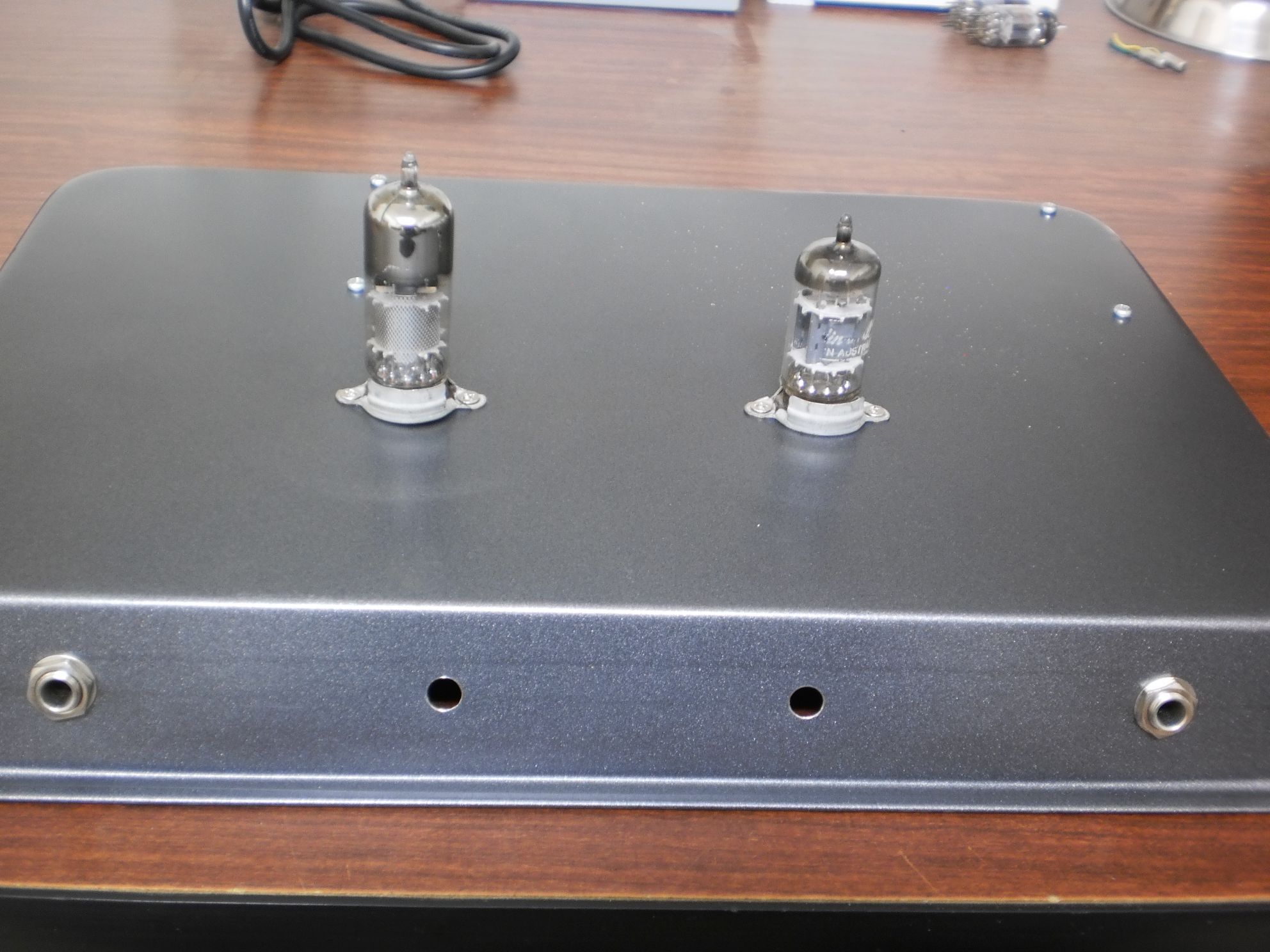
Some progress – the chassis was prepared with holes for the controls, valves and spring tank. As mentioned, a 12V plugpack supplies power to the valve heaters and a toroidal transformer steps up the 12V AC to generate the HT for the valves.
An Accutronics 8EB2C1B spring tank was at hand and is ideal for this build with an 800 ohm drive impedance. These tanks are readily available as a spare for the Fender Blues Junior amp both here in Australia and O/S.
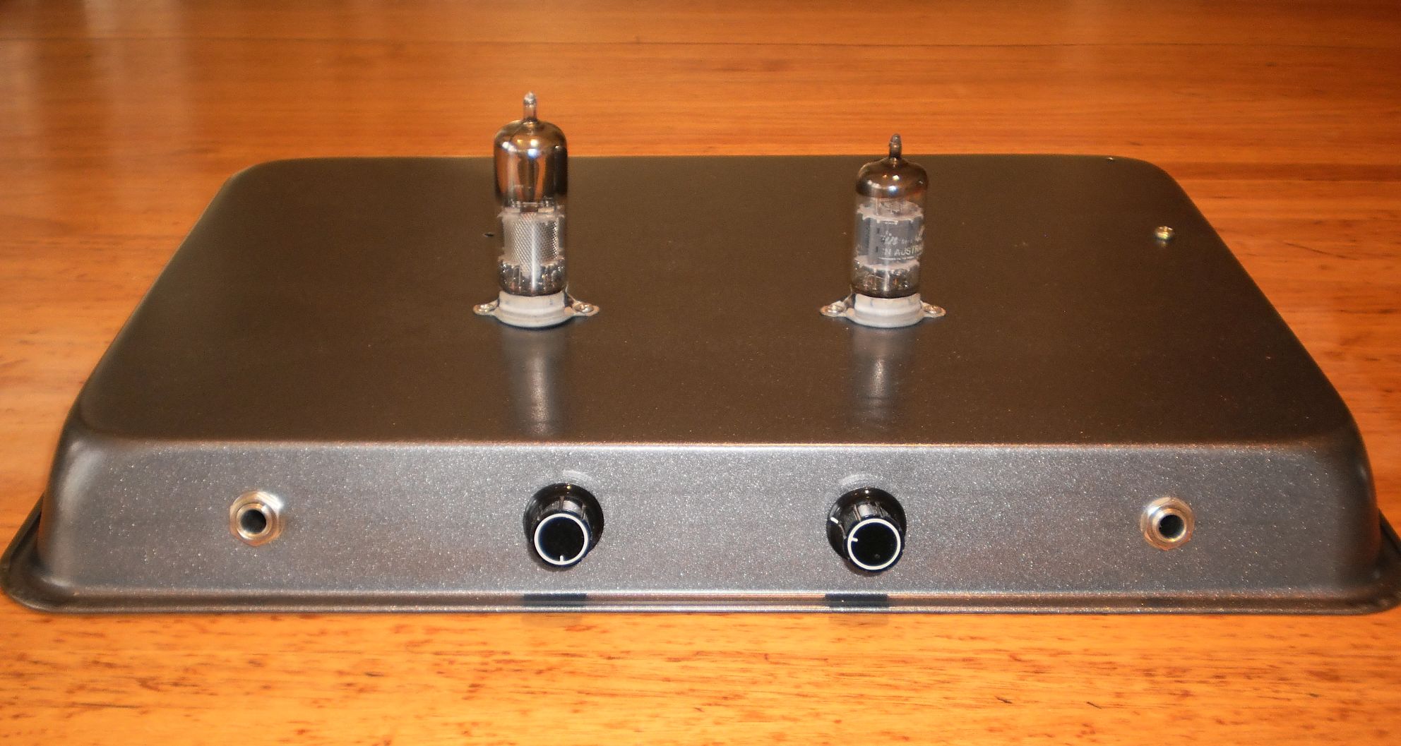
Have now completed the Lamington Reverb and pretty happy with it. Firstly, a photo of the finished reverb unit.
From left to right: input, dwell, mix controls and output.
Also visible is the 6BX6 tank drive valve and a 12AX7 preamp and recovery valve.
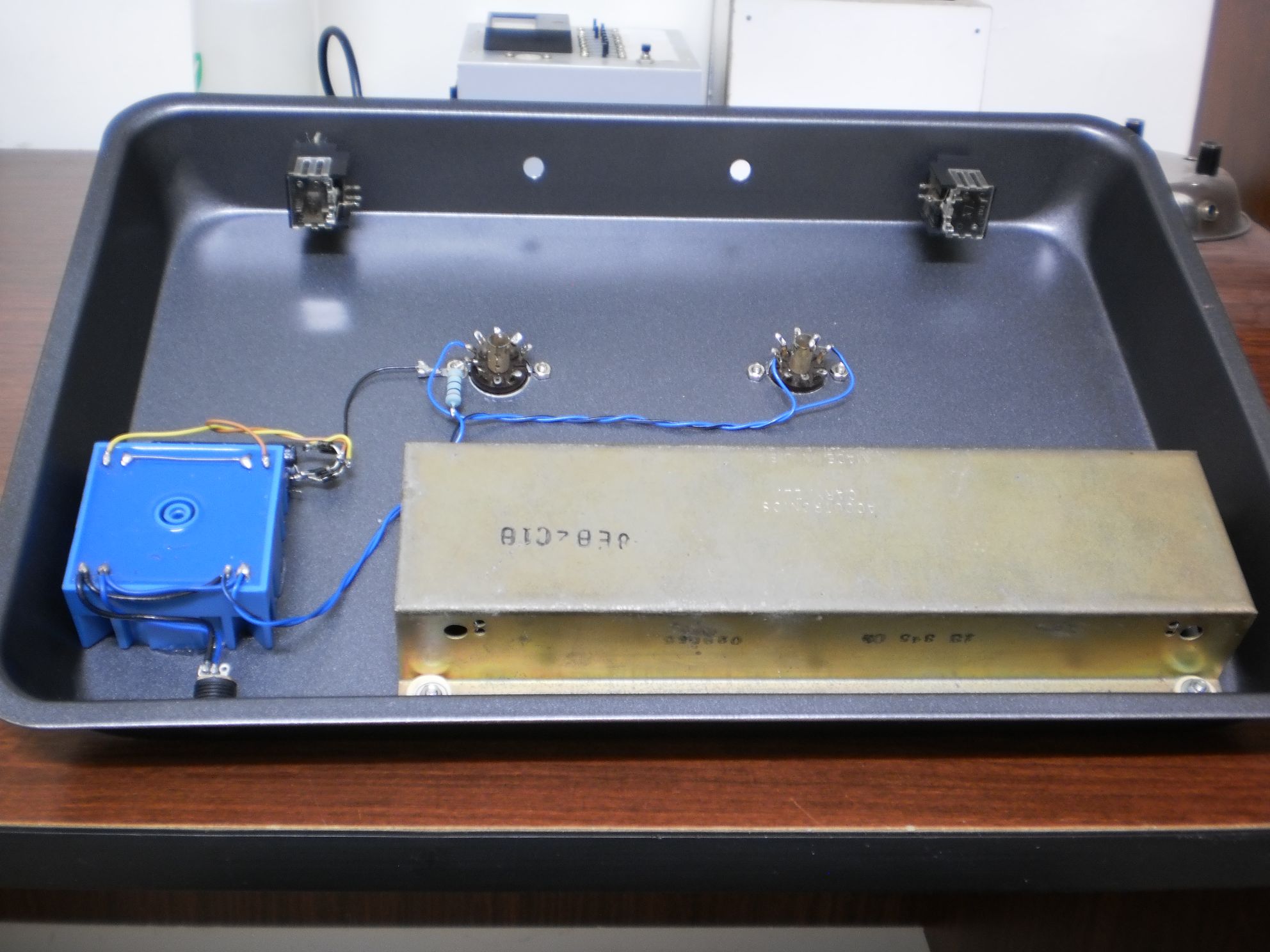
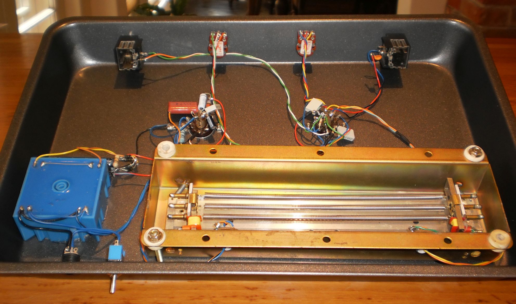
And an underside photo. Not a lot to it – a 12V to 240V toroidal transformer, the reverb tank, and some components clustered around the valve sockets. You can click on the image for more detail.
Here is the schematic for the Lamington Reverb. You can click on the image for more detail.

It is a simple circuit, but works well.
The input signal is fed to the first gain stage with the dry signal fed straight to the MIX control from the cathode. This first stage drives the current source pentode via the DWELL control. This determines how hard the tank is driven and changes the reverb tone as a result. As discussed, the tank drive circuit is taken from the Channel Road paper and provides current drive directly to the tank eliminating a drive transformer. The tank used in the prototype is an Accutronics 8EB2C1B which is used in the Fender Blues Jnr and is readily available here in Australia and overseas. Its drive coil impedance is 800ohm and is ideal for the constant current driver which is a commonly available 6BX6 (EF80). The output of the spring tank is fed to the other half of the 12AX7 input triode and the output of this valve is fed to the mix control and output socket.
The power supply is a simple arrangement using a 12V 1A plugpack which feeds the heaters and a second transformer which steps up the 12V to a high voltage for the valve HT.
Some construction details to come.
Some comments on constructing the Lamington Reverb.
If you are using an EI step up transformer, I suggest waiting before mounting it. With some extension leads on the transformer, move it around to find the position that induces the least amount of hum and mount it there.
You may note that I have used fairly large values of HT filter caps for the prototype. This was necessary to eliminate any HT hum from being introduced into the unit.Re suitable valves for the Lamington Reverb, the 12AX7 is readily available. The 6BX6 is no longer manufactured, but was used by the squillions in the day in B/W TV sets. It can be substituted with about any RF pentode such as the 6AU6, 6EJ7, 6ET6, 6CB6, EF94 etc
The Accutronics 8EB2C1B reverb tank is readily available from Evatco here in Australia or from Ebay. You may wish to use a longer tank which would work fine in this unit as long as it has a high impedance (600 or 800ohm) drive coil.Re the transformers, the plugpack is a 240V to 12V1A AC unit. The stepup transformer I used is a 10VA 240V to 12V toroidal transformer wired backwards. Just about any low power 240V to 12V transformer could be used – just check its location with respect to the reverb tank as mentioned to minimise hum.
So overall, I have been very happy with the Lamington Reverb – it sounds very lush with no unwanted noise and hum. The ability to vary the drive to the tank with the dwell control is an added bonus to change the character of the reverb tone.

Hi Grant. My first amp build was a Lamington. No experience, no skills and just a circuit diagram to work from. I’m now very much hoooked on tweaking/fixing/building amps. Thanks (I think).
Where in the signal chain of the lamington amp would you put the lamington reverb? As an effect prior to the amp? After the first gain stage? Where would you suggest? Cheers.
Jeff
Hi Jeff, really great to hear you have successfully built a Lamington amp.
With regards to my Lamington reverb, it is designed to be connected to the front of an amp, as a Fender 6G15 or an effect pedal.
Regards, Grant
Hi Grant. Have no much experiences with tube amps building (just a few mods) but this looks like very nice project for the beginners.
Is there any easy way to add footswitch to this circuit?
Thanks for sharing.
Regards, Radim
Hi Radim,
Thanks for your interest in the Lamington Reverb. Yes, it is quite easy to add a footswitch to the circuit. Just add the switch between the reverb return output (ie pin 7 of V1b) and ground. Have fun!
Hi Grant,
Thank you for the great project. Reverb was sucessfully build and I still really like it.
Do you think it is possible to use two reverb tanks and to switch between them when play? My first reverb tank was MOD 8EB2C1B. Sound was perfect but wanted longer decay, so I bought MOD 9EB3C1B (both have 3 springs). Now Im satisfied (at least for more surf stuff) but sometime miss the sound of shorter one. There was something in the sound which cannot be simulated just by turning the knobs.
What would you suggest?
Cheers
Hi Radim, great to hear you are enjoying your Lamington Reverb unit. Re switching between tanks, it could be achieved by using a double pole double throw (DPDT) switch. The middle (wiper) contacts would be connected to C4 for one half of the switch and pin 7 of V1b for the other half. You would then connect the “hot” leads of each reverb tank to the outside contacts of the switch. The switch would then select between the tanks. Hope that helps!
Grant,
I know I’m really late to the game, but I had a question about the schematic.
It looks like you’re feeding 12v into only one of 2 heaters, did you wire the 12ax7 heaters in series to get the voltage down? Will the heaters survive taking double their max voltage? Or am I missing something. Thanks for your work and help.
Hi Jesse, in my reverb unit I wired both of the 12AX7 heaters in parallel to achieve a 6.3 volt .3A connection. This was wired in series with the 6BX6s 6.3 volt .3A heater so that the 12v supply is equally divided between them. HTH!
I observe that there is mains isolation through the psu and toroidal step up transformer.
1. The circuit diagram references ‘chassis earth’ but there is no earth connection on your diagram. Please elaborate.
2. Would you please explain how safety is maintained (a failed solder joint could expose 300+VDC to the chassis and hence the guitar and player in the absence of any other earth).
3. Would you also provide details of the source of your 12VAC PSU with an earth pin?
I am 90% through this build and need to be sure it is safe. Thanks.
Hi, yes my design provides mains isolation via the 12V plugpack. This means that the chassis of the reverb unit is isolated from the mains, but as you say is not earthed. Typically, when used with an amplifier, the signal earth of the reverb is connected to the amplifier earth. Either way, the reverb unit is safely removed from the mains.
Hi Grant,
Just wondering, the upside down triangles; obviously the ones that say chassis Earth makes sense but where do the others go- do I also Earth them to the chassis?
Thanks so much
Hi Dan, yes the “upside down triangles” are all ground (earth) connections.
Hi, I’ve been looking at your stand alone Reverb. I’ve already built your valve tester.
Just a query or two.
1. Why the power pack and then the step up back to 240v, why not just go with 240v supply and a small step down to 12v for the heaters?
2. I know that the pin outs are different, but the EL84 is more readily available than the 6BX6, any reasons for not using this?
Hi Syd,
Great to hear you have built my valve tester.
Re the Lamington Reverb, I assume you mean connecting the unit directly to the mains 240V? If so, that is not a proposition for safety reasons. There would be no isolation between the reverb and the 240V mains meaning that there is a real risk of the mains lead being reversed making the chassis live. The plugpack used in the Lamington Reverb provides full isolation for the circuitry.
Re the choice of 6BX6 for the tank drive valve, I used it as it has a much reduced heater current requirement than an EL84. There are a heap of valves that can be used in place of the 6BX6 and they are listed in the description. If you get stuck, let me know and I can send you one for the cost of postage. Cheers!
Thanks for the clarification Grant
Hey I’m reading this article for the first time and this is set to be my first build ever! Can you elaborate on why you can’t just use 240 mains, ground everything to earth and use a 240 to 12 for the heaters? Is it because the springs in the tank could possibly hit chassis and cause chassis to become live? Thank you I’m so new I’m not even out of the womb yet!
Hi Scott, your question is asked from time to time, and at first sight it looks like a good way to eliminate a transformer. However, there are serious risks with doing this. If the neutral link should float, the whole circuit would be live to the mains active including your guitar plugged in to the unit. And even if the neutral link was good, the unit could be plugged in to a mains outlet that had active and neutral reversed. This is a common occurrence and would put the active 240V directly connected to the ground connection of the unit. All said, this why any circuit MUST be isolated from the mains with a transformer – this mains isolation makes sure that any faulty mains wiring scenario will not cause a serious safety issue with the device. Having said that, my Lamington Reverb uses two inexpensive transformers in the supply and besides being low cost, they provide a completely safe power supply. Cheers!
Would an EF86 work well as a drive tube? I also have a few EF36 valves that I’d like to try!
Hi Andrew, an EF86/EF36 is not really suitable for the drive pentode in the Lamington Reverb. They are lower current preamplifier valves, rather than a higher current RF pentode like the EF80/6BX6. If you get stuck finding a 6BX6, email me and I can supply you with one. Cheers, Grant
Hi Thanks! Think Ive got an old Telefunken 6au6 that I’m going to try.
Hi there,
Great reverb design. I have built this but I used a tube town toroidal that is providing both the HT voltage as well as heater voltage (6.3V) eliminating the plug pack/step up combo.
My problem is the reverb has quite a pronounced hum when I blend in the reverb, full dry the hum is gone. I’ve implemented a hum loop block circuit for the signal grounds but that hasn’t helped, as well as elevated the heater tap onto the cathode of the the 6BX6. Also played around with reverb tank position but that hasn’t helped either. It’s a low frequency hum.
Also chopsticked various signal and power wires to no avail so I’m stumped, any ideas?
I’m guessing maybe something to do with heater wires, I noticed in your schematic that they are running off of a 12V arrangement where as mine are coming from 6.3V off the toroidal.
Any ideas/help would be appreciated, this reverb has a lovely tone besides the hum problems.
Regards,
Dale.
Hi Dale, it can help if you can confirm if the hum is 50Hz or 100Hz. If it is 50Hz, you have a magnetic hum induction issue. If it is 100Hz, it is power supply related. Cheers, Grant
Using a graphic EQ to target frequencies, a lot of the hum is reduced when I cut at 100Hz but that is the lowest the EQ goes down. I will say that I am using a tank with an output of around 600ohm versus the 2500ohm of the suggested tank so not sure if that is causing issues?
Losing a lot of general volume when I use the reverb unit versus plugged straight into the amp too but not sure if that is normal behaviour.
Cheers,
Dale.
Hi Dale – Hmmmm….hard to say if that is mains hum or power supply hum. The tank is fine with a 600ohm input impedance. There should not be a significant reduction in volume if the reverb is bypassed – I suggest you recheck your wiring – perhaps the hum issue is related to the volume drop? Cheers.
Hi dale,
At first I too had no hum when the mix knob was set an min, but lots of low frequency hum when the mix knob was set higher.
It turned out I used a 150r resistor instead of 15k to V2 pin 7 by mistake. Using the correct resistor solved my issue. Maybe you made a similar mistake?
Regards
Joel
Hello Grant,
Thank you so much for the schematics this looks awesome. I’m building one right now, and if i didn’t just get a nice little tube amp (without a reverb tank) i’d be building a Lamington amp to go with it.
I’m wondering what you thought about putting an SPDT switch just where the input comes in creating the option to “true bypass” to just before the output, in the form of a stomp toggle. Obviously I won’t be smashing my biscuit tin version and i never stomp my stomp boxes anyway but yeah, can you think of any reason why this wouldn’t work or would be a bad idea?
Thank you for your time,
Jonus
Hi Jonus,
Thanks for your kind comments. Yes, you can add a true bypass to the reverb, and another option is to add a SPST switch across the reverb tank output – this is how Fender amps switch the reverb in and out. Have fun!
Hello Grant,
Thank you for your prompt reply. Sorry but I’ve got some noob questions. This is the first audio-related circuit I’ve ever made, having made coil/Gaussian guns in high school from disposable camera flash circuits and other than that only high school physics pracs.
I assume the ground from capacitor 8 is also going to the chassis, or is it going to signal ground?
Is the signal ground essentially a line from the input ground and the output ground with all those signal grounds (like from capacitor 3, and resistor 3) connected to that line?
Thanks again for your time,
Jonus
Hi Grant
Nice build, I like the idea of using both signals from plate and cathode of the first stage.
I am doing something similar but with a bigger input impedance reverb tank and a 6DX8 as a driver and recovery.
I wonder if you have noticed any “phaser effect” as it seems signals are out of phase when they are mixed in the output pot.
Hi Niquel, yes there is a real advantage to using a pentode as a current source to drive the tank. There were no phase issues with the prototype as reverb by nature involves random phase additions and cancellations meaning that it does not matter how the reverb signal is mixed with the dry signal.
Hello, Some one is helping me build it as i have no idea.. but i have a gibbs tank that is 4AA1C1C which input is 8 ohm and output is 500ohm.. are we able to use this tank?
many thanks
Hi Wayne, the 4AA1C1C tank is a low impedance tank with those specs. My design requires a 600-800 ohm input impedance and approximately a 2275 ohm output impedance.
Thanks so much for clarification. Any suggestions what we can build with this tank any links to plans that would suit please? Thanks so much for helping.
Hi Grant, Fender reverb circuits generally couple the drive tube to the tank with a transformer. I’m wondering why you chose a capacitor instead?
Thanks!
Hi Larry, the rationale to use a directly driven high impedance tank with a pentode is discussed in the project description.
Hello Grant. I built this and it works great. However there is a buzz which increases when I turn up the volume with the reverb engaged. There is no buzz when just the dry signal passes through. What would cause this? Thank you.
Hi Issac, a couple of things you might look at. If the noise decreases when the tank is moved, you will need to re-orient it. Also, make sure that the junction of the two valve heaters is grounded.
Hi Grant,
In the photo there appears to be a resistor attached to the heater lead. Should I be adding this to my circuit and at which rating?
Thanks
Hi Lorin,
You have a good eye! The prototype did use a resistor in the heater circuit to drop a couple of volts as I used a 14V plugpack. If you use a 12V plugpack, no resistor is required.
Hi Grant,
Have recently built the Lamington III amp. It sounds awesome.
I’m wondering if it’s possible to build the Lamington reverb with the power supply coming from the Lamington III instead of using a plugback.
Thanks
Hi Adrian,
Great to hear your Lamington III build went well.
It is not possible to power a Lamington Reverb circuit from the Lamington III power supply as there is not extra power available from the Lamington III supply. Regards, Grant
Hi Grant. I’ve had a crazy idea, but not sure if it would work so wanted to run it past you to see if I’m nuts or not.
I’d really love to build this reverb circuit into the 15W Lamington, and been trying to figure a way to do it. Assuming the power supply was beefed up to handle the extra load, could you slip this in at the beginning of the Lamington preamp after V1a; and drop the preamp valve (V1a) from the reverb circuit? Basically replace V1a in the Lamington with the entire reverb circuit? The only difference I can see between the two circuits is the 68K grid stopper resistors(?).
Link to a schematic with my idea:
https://andersonhomenetwork-my.sharepoint.com/:i:/g/personal/graeme_homenetwork_net_nz/Ebzr_anT52xDv-Q0divujO4B9klAXK5Bg0u22yJYeJpqXA
Note: there’s a tremolo on there too, still working on that guy…
Thanks Grant.
Hi Graeme,
My thoughts with any integration of reverb in an amp are that care needs to be taken with not only blending dry and wet signals but taking into consideration the different signal levels and impedances required by the tank drive and return circuits as they integrate with the preamp stages. The Lamington Reverb was designed as a stand alone reverb unit and that application requires quite different design to a built in reverb. A quick look at your circuit shows that the use of V1a as the reverb preamp means that when reverb is switched in, the dry signal only has two rather than the three gain stages required for the Lamington.
If you want to see examples of commercial amps that integrate tanks into a preamp, look at the Fender Deluxe Reverb circuit.
Thanks Grant. I had a feeling that may be the case, so I have another drawing that switches the whole reverb circuit after V1a:
https://andersonhomenetwork-my.sharepoint.com/:i:/g/personal/graeme_homenetwork_net_nz/EUzPsn0hAotOliL0wsFr-ccBG0ZaPuSSE8P8WoE7VrQk_A?e=2hi2G0
However, sounds like there’s more to it than just squishing the circuit in verbatim, looking at this new drawing am I correct in saying the signal will be amplified from V1a (which the reverb is not designed for) and adding the circuit in will change signal path impedances in those stages too? Sounds dangerous way down there in the first stages.
Thanks for your suggestion of looking at the Princeton Reverb. That design was the basis for a potential “option 3” I was cooking up; injecting the circuit between the last preamp stage and the phase inverter. My concern with this approach was that the Lamington reverb as designed to amplify tiny line-level signals, at this end of the amp it might not be strong enough to make much of a difference.
I have a couple of 6BX6 valves and a 800 ohm tank which is why I wanted to try your design in the 15W Lamington, would be sweet! Do you think with a bit of perseverance (trial and error) it could work, or do you think it’s too hard (full disclosure, I’m a beginner – but you probably guessed that already 😀 )?
Hi Graeme,
Yes, integrating a reverb circuit into an amp does involve a range of design issues. My reverb unit was designed to be a stand alone unit and can’t be simply added to an existing preamp. A better option is to rebuild your preamp along the lines of a typical Fender reverb amp. HTH
Thanks Grant, appreciate your help. Taking this all on-board I think what I’ll do is make an amp using some “known-good” plans, but build it in a way to let me add a reverb later once it’s “bedded in” and I know a little bit more about what I’m doing. Really keen on getting a high impedance capacitor coupled reverb working, even have the right tank waiting to go :-).
Hi Grant, thank you for this really cool design!
I was very curious, so built one and did a direct A/B comparison to a Fender ’63 Reissue Reverb Unit.
With some small tweaks there is almost no difference, the Lamington sounds even a bit fresher to my ears.
I made a short video, I hope you like it. If you don’t mind I’ll leave it online:
https://youtu.be/HWlHYcYR6J0
Hi Andreas, thanks so much for the update on your Lamington Reverb build – it looks good!
And thanks also for the Youtube clip – it confirms that current drive is preferable to voltage drive with a more extended high end. Cheers!
This looks like a great design. Thanks for sharing. I scored a few high impedance tanks, so called F tanks. Will these also work with an EF80 driver tube?
Hi Mischa,the Lamington Reverb design suits any reverb tank with an input transducer impedance of anything higher than 600ohm. Cheers
Hi ,
I really want to try it 🙂 Thanks for share
Maybe a stupid question 🙂
A heater at 12V AC work really ?
I was thinking the maximum is 6.3V ( tolerance 10% up or Down )
or DC heater can used but some other part
Hi Seb, in the reverb unit the heater supply is 12V but the two valve heaters are wired in series – 2 X 6V heaters in series to make for a 12V supply. HTH!
With regard to the two tank idea, one long one short using change-over switches, If you use triple change over switches you could have two LED’s driven by a resistor and diode from the heater circuit with different colours for the two tanks using the extra pair of contacts, always know which tank you are using . The sub-min ones are easy to get on ebay from China (and cheap)
Hi Grant,
I am eager to start building the lamington reverb and have all the parts. There is however a little twist.
I have just built rick-tone trem-o-drive from part from an 60’s organ. The trem-o-drive also uses cheap 12v transformers, but are designed for 120v so there is a voltage doubler in the curcuit.
The organ I took parts for however had a “normal” power transformer with 6.3v tap and 220v so I used that one. I altered the circuit slightly for 6.3v instead of 12v and made a full bridge rectifier instead of the voltage doubler. It works great!
I am now thinking about building the lamington reverb in the same chassis, using the same transformer. Tremolo and reverb are about the only effects I use and it would be cool to have them both in this old chassi 🙂
I’m sure my transformer can supply both tremolo and reverb, but I’m still pretty new to this and have a few questions I would hope you would be able to answer.
1. For the 6BX6 heaters, will it work to use one of the 6.3v cords to pin 4 and the other one to pin 5?
2. The filtering after my current circuit’s B+ will probably not work that good for the lamington reverb.
Would it work to just split the path right after the rectifier (juncion D3 and D4 in your schematics) with one filter path for the tremolo and one for the reverb?
3. If 2 is not possible, would it work to have two different rectifier path? Two full bridge rectifiers with different filtering.
Thanks in advance and also thank you so much for your awesome site!
Regards
Joel
Hi Joel, thanks for your interest in my reverb design. Regards to your questions, yes, the 6BX6 can be wired to a 6.3V winding to pins 4 and 5. The 12AX7 is wired with 6.3V winding connected to pins 9 and then pins 4 and 5 strapped together. You can feed the Lamington reverb HT to a decoupled HT node from your tremolo supply. Hope this helps!
Hi Grant,
Thanks for your reply.
My build went well. It works fine with 6.3v heaters and sharing chassis with the tremolo. I used an 4EB2C1B (long 2 springs) tank as they were used in Fender Reverb 6G15 and I like the sounds of those. It sounds great!
BTW, you should set up a donation link on this awsome site. I for sure would use it and I don’t think I’m alone 🙂
Regards
Joel
Hi Joel, great to hear your build went well and thanks for your encouraging comments. Re a donation link on my site, I was always motivated to provide assistance for builders at no charge, but if there was demand for a donation link I might consider it!
Hi Grant. just built one of these with parts form an old valve radio from the 1950s (it had 2x EF80 and a useable HT transformer and valve sockets). The reverb tank was pulled from a 1980s Fender M80 solid state combo.
Sounds great, thanks for all your work on using old valves.
I tried to find the schematic for the original TV special but the forum it was posted on has links to a hosting site that blocks access now.
Could you repost the schematic or email it to me.
Cheers, Dougie.
Hi Doug, good to hear you liked the Lamington Reverb. I have emailed you the schematic requested. Cheers
Hey Grant,
I’ve been building this reverb for a week now trying to figure out where I’ve gone wrong…
I cant get any signal from input to output, tubes dont seem to be heating up at all and when I gain the signal on my mixer, I can hear a “heartbeat” at 100bpm (this is gained way beyond what any line in would be mind you)
I first tried the circuit using a 6AU6 with no changes to the circuit, I have a feeling I broke it (the bottom started glowing brighter than expected and then went out) so I’ve hooked up a 6BX6 and still nothing…I get a hiss when I turn the mix knob up but the gain on the mixer is so high that I would expect some sort of hiss.
Just wondering where you think the problem may lie? I think I’m just goingto pull it all apart and start again more carefully since I am a beginner at all this.
Cheers,
Brodie
PS. This site is amazing, Thank you
Hi Brodie,
Great to hear you have embarked on building my reverb unit. It certainly sounds like you have several issues with your build. This is not uncommon when you first start building gear – I remember building valve projects in my teens that didn’t work. I tore them down and rebuilt them until they worked. This may sound like wasted time, however I learned a lot about construction methods and how they worked as a result. So perhaps your issues present a good opportunity to learn a lot about valves and electronics. All the best!
Thank you for your work! Looks like a super solution!
Will this transformer work i n conjunction with a 1A 12VAC adaptor?
https://elektronik-lavpris.dk/p103220/bvei4811172-transformer-10va-230v-12v-833ma/
Hi Flemming, yes, that transformer is fine for a step up transformer for the Reverb
Hi Grant,
I am tempted to build your reverb project. I already have some 6BX6 valves from my Grandfather’s spare collection of values. Just curious, you draw the 6BX6 as a tetrode. Is one of the grids not being used?
Hi Conrad, yes the suppressor (G3 grid) is connected to the cathode of the 6BX6. Cheers
Hi Grant,
I have just constructed the reverb unit and it works very well. I have used a long 3 spring tank and it produces a nice smooth reverb and good depth. I’ll send some photos soon. One odd thing, the dwell pot when turned down to its limit causes quite a buzz. Is that a problem with the pot?
Cheers,
Conrad.
Hi Conrad, not sure what the issue is with your dwell pot – perhaps instability issues when the control is backed off? Checking with an oscilloscope would confirm this.
Hi Grant, thanks for the suggestion. I have now placed the 1.5 k resistor between the pot and pin 2 of the pentode because the problem occurs at both ends of the pot travel which does prevent the buzz. It still performs very well in spite of this issue. I am continuing find the source of the problem.
Regards,
Conrad.
HI Grant,
This looks amazing!
Sorry for my ignorance but I was wondering if you have a wiring diagram from this; I am hoping to do it on a Circuit board?
thanks again
Dan
Hi Dan,
I don’t have a wiring diagram for the Reverb unit unfortunately.
No probs. Thanks Grant. Keep up the good work.
Can’t wait to make this!
Hi Grant,
Sorry me again. Would a Nuvotem Talema Toroidal Transformer 70052K which is 15VA be okay?
Hi Dan, if the transformer is a 240V to 12V transformer it would be fine.
Really like the idea of adding this into a weird amp I’m building, use it as a front ended reverb, so just like it’s designed to be a stand alone unit, but all in one combo! Very easy to work out however, what voltages are the tubes seeing from your power supply stage? I see it goes from 240 to 12 to 240 (I understand the isolation) and is then rectified and filtered… then resistors at ht 1 and 2… just wondering if I tap into my existing transformer and use resistors to match the voltage wanted by v1 and v2 in your diagram? Thanks!
Hi Scott, yes in principle you could power the Lamington Reverb from an existing amp if it allowed for the extra heater and HT requirements.
Hi Grant, just discovered your site, big fan,
Great design, love the simplicity.
Some tube amps can be run quite musically at lower than their specified +ve. Do you know if this design can be run successfully at lower voltages, if so what is the lowest voltage?
Cheers
Camelfish.
Hi, thanks for your interest in the Lamington reverb.
As you say, valves can be run at lower voltages but linearity and headroom suffers for clean signals.
Cheers, Grant
Hi Grant.
Thanks heaps for putting your plans online, I’ve built one of these now and it works really, really well. There’s more ‘verb than I can use after ~3/4 on the dials, and it turns into something completely different from those settings but still sounds very cool, lots of control from a slight colouring to insane but still with control to dial it in how you like.
A couple of things left to do, I didn’t make this as a stomp box with footswitch as it seemed a bit delicate having the valves/transformers out the top of the aluminum chassis so I’ll need something to put it in, and I’ll probably make a faceplate to “pretty it up” a bit (I’m experimenting with making faceplates so this is another opportunity). Also – thought I might get away with it but I put a jack on the back that shorts the signal to earth from reverb side of V1b pin7 using a footswitch but it turns out sending the signal all the way down a cable to a footswitch isn’t a good idea, turns into a giant aerial and is very noisy so plan “B” is a 12V relay – yet to work out how to do that but when I’m bored one day I’ll have another look at it. The circuit is easy enough just going to have a think about if I should use the existing 12V circuit or build a separate one to keep the valve heaters separate from the relay circuit.
Anyway, thanks again for publishing the schematic and write-up, was very fun making this and it works really well
Hi Graeme, thanks for the info on your build – well done!
Hi Grant,
Thank you so much for your work! Two questions.
1. What part changes would I need to make the schematic work with 120V coming from the wall.
2. Would you recommend this as a first shot at an electronics project with tubes?
Hi David, to build the Lamington Reverb to operate in the USA, use a 12V step up transformer with a 230V primary.
HI Grant,
I tired my best to make the tube reverb but obviously I dont have the skills. Would you be open to wiring this up for me? (I have the all the parts). I have blown the transformer a few times (struggling with the 12v to the heaters as I keep creating a short Circuit).
Of course I will pay for your time, materials and shipping to the Uk.
Would love have and really struggled – I even wired it on a bread board and put fuses in.
Thanks so much
Hi Dan, I am sorry to hear you have had issues with building the Reverb. It reminds me of when I started building valve circuits many years ago and I had numbers of failures along the way. Unfortunately I am not able to assist with troubleshooting your unit. Can I suggest connecting with a local amateur radio group or a Youtube radio channel (there are several based in the UK) to ask if a seasoned technician would take you under their wing? All the best!
Hi Grant,
Will do Thanks so much for all of your good work! Keep em coming!
Hi Grant,
Am I reading the diagram right by hooking pins 4 and 5 of the 12AX7 and pin5 of the 6BX6 to ground. While the pin 4 of the 6BX6 should be hooked up to the +12 pin of the dc jack, and pin 9 of the 12AX7 should be hooked up to the ground pin of the dc jack.
Also since the reverb tank has an insulated input and a grounded output, if im using RCA cables to make the connections, should I only connect the shield of the input cable to ground. Or should both cables be connected to ground on one side of each cable. Thanks for your help!!!
Hi David, yes, the heater pins on the 12AX7 (4,5) and 6BX6 (5) are connected to chassis ground and pin 4 of the 6BX6 and pin 9 of the 12AX7 connect to either side of the 12v AC input from the plugpack transformer. And both of the screen or shield connectors of the reverb tank need to be grounded. Cheers!
Hi Grant
I just finished building your reverb unit. Somewhat to my surprise, it actually worked. Not that I doubt your design, but it was a first for me. So thank you very much for publishing the schematic.
I still have one question though. Why is there a different HT for the 2 valves? As far as I can see, one is just better regulated than the other.
Best regards (and the best for next year)
Patrick Meeus
Hi Patrick, firstly thanks for your kind donation – helps to keep the new designs coming!
Great to hear your Lamington Reverb works well. The reason for the separated HT for the two valves is to provide isolation between the two stages. Without the additional resistor and capacitor in the HT line, signals generated in the Tank driver valve can be impressed on the earlier stage causing instability or hum. If you look at the schematic for any guitar amp you will see the combination resistor and capacitor between the output stage HT and the preamp HT that we refer to as a “decoupling network” Best regards!
Hello,
Can it be used in an effect loop on a mixing desk? I mean with a line level (cd player type) as input ?
I could reduce the input gain by using a variant of 12ax7 (12au7 / 12av7) for example.
Or is it only designed for smalls signals like guitars ?
Thank you.
Hi David, the Lamington Reverb was designed for guitar levels and is not suitable for line level operation. Regards, Grant
Hello,
I would like to make this reverb by adding a line input to use it in an effect loop on a mixer or with a synth.
Since the input level is intended for a guitar, when do you think about adding a ~470k resistor with a capacitor in series, to reduce the input level ? See also to replace the 12ax7 by a 12at7 see 12av7 to reduce the gain ?
Thank you.
Hi David, as mentioned, the circuit would need a redesign to operate at line levels and unfortunately not as simple as reducing the input signal – it also needs the output level significantly increased as well.
You can use a reamp at input and direct box at output and then connected directly to the mic ( the direct box ) in of the mixing desk . Work like a charm ! But one of the reamp or Direct box need to be grounded i think .
Hi Grant,
How well does this design “drip”? Does it hold up well against the 6G15 for surf?
Hi Pete, thanks for your interest in my reverb unit design – you can check out a Youtube description of my design here: https://www.youtube.com/watch?v=HWlHYcYR6J0&ab_channel=MONOKINI
Cheers, Grant
Hi Grant, I know I am way behind in doing this build but wanted to let you know how much I enjoyed it. I had fun building and it sounds good. I do have some hum but if I keep the dry signal stronger than the wet I can cut hum. At this setting the reverb effect is suttle yet super noticeable. You notice it when I bypass it. Thanks for all the info.
Hi Randall, great to hear from you and that your build went well. Any hum in the reverb unit is always due to orientation of the reverb tank in relation to power transformers. I suggest you move, invert or otherwise reorient your tank – it should minimise or remove any hum. Cheers
Hi Randall, Just wondering if you ever got a solution to your problem as i seem to be experiencing the same thing as you. I know the hum isn’t the reverb tank (the tank hum (when I place it near the transformer is a different frequency). Thanks
Hello Grant, Just wanted to say thanks so much for this schematic. I’ve successfully built it and it sounds great! Even into an amp with a bit of gain. I did find that the unit had some home with my power source but managed to rectify this with an extra filter https://el34world.com/Forum/index.php?action=dlattach;topic=26332.0;attach=86241;image
My only question is… Is it possible to squeeze just a touch extra volume out of the unit? Only just a touch though. The volume drop is only just noticeable. If not I’ll add a clean boost to the unit.
Hi Chris, it is not really possible to increase the level of clean tone from the reverb without a redesign. As it stands, the clean output level of the unit will be around 90% of the input level. Hope that assists, Grant
Hi ,
Thanks for sharing this reverb
I want to know why in Channel Road paper use a 68K resistor grid stopper after the Dwell pot , why you remove it ? for Hiss ?
I don t know the miller effect for a Pentode , but maybe like a 12AX7 with 1M grid leak , a grid stopper is often in this place or even a lowpass filter . Maybe an hpf also in front of driver , because the spring hate LF rattle 🙂
What your opinion please ?
Hi, thanks for your comments. A grid stopper could be used before the 6BX6 but I found it wasn’t required in my prototype.
Hi Grant.
It’s one of those projects that it happens you have all parts readily at hand. I’m just about to complete it. I’ve found a few comments about putting this reverb in-line. Have you ever considered such design option? Or maybe suggestions what should be altered from original design? Thank you for all your work and best regards.
Hi Martin,
Great to hear you are building the reverb. Re modifying the reverb for line levels it would require a redesign. The original Lamington Reverb was developed to plug directly into a guitar amp like the Fender 6G15. Cheers
Hi grant,
just wondering what type of capacitor you used for the polar 1uf 350v coupling cap between the 6bx6 tube and the spring reverb tank? I have a hard time finding a quality suitable cap and wondered how you went on about that?
Also wondering what a non polar one would do to the circuits operation?
Hi Elliot, I used an ordinary 1uf 350v electrolytic capacitor as it is non critical in this circuit. Any cap from 1-2 uf is fine. Enjoy your reverb!