
Design | Construction | Components
A goal of this amp design was to keep the costs of construction to a minimum. In prototyping this amp, I was very mindful that most people constructing it will have limited metal working experience. In addition, commercial rack cases and cabinets can be rather costly.
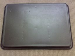
A solution to these challenges came in the form of a readily available, low cost “Lamington” cake baking tin from Big W or K-Mart. An inverted cake tin provides an attractive, teflon coated chassis which is ideal for the amp.
!! Warning !!
It needs to be said that this amp generates potentially lethal voltages.
It cannot be overstated that you need to exercise extreme caution when measuring voltages etc., on a working amp. NEVER hold the chassis with one hand while you are probing with the other hand. Put one hand in your pocket and probe with the other with the negative multimeter probe firmly clipped to the chassis earth point.
Don’t forget that even when the power is turned off, potentially lethal voltages may still exist in charged capacitors in the amp. Before working on or modifying the amp, wait for 5-10 mins to allow all capacitors to discharge.
A voltage check will tell you if there are still voltages present.
Working on valve amps need not be dangerous if you apply due care, common sense and maintain a healthy respect for over +300V of high voltage.
I present these amp designs with the understanding that anyone building them has taken the time to consider the relevant safety issues involved. Your safety is important!
There are a number of holes to be drilled in the chassis, and reference to the layout diagram will allow you to mark out the chassis. I recommend that you mark out grid lines for the holes with a soft pencil. It really helps you see where you are going.
There are holes for the transformers, holes to pass the wires from the transformers under chassis, holes for the valve sockets, holes for the front panel controls pots and holes for the mains cable entry, fuse holder and mains switch.
It is highly recommended that you “centre-punch” each hole before you drill it. This will make sure that you drill the hole accurately without the drill bit wandering off target. You can centre-punch the hole with a proper centre-punch or use a large nail as a punch.
The drilling of the chassis assumes that you have or can borrow an electric drill with a range of drill bits up to 3/8 inch or 10mm. When you punch the chassis or drill a hole, always place a block of wood on the underside of the chassis. This will ensure that you do not damage the fairly light steel of the chassis.
There is a technique to drill the larger holes (up to 10mm) without the drill bit grabbing the chassis and bending it out of shape. Simply start drilling from a smaller pilot hole and then change drill bits to progressively larger bits to drill progressively larger holes.
If you find that your drill grabs the chassis a bit aggressively and bends the chassis, all you need to do is place your block of wood on the underside of the chassis, and gently tap over the top side of the hole with a hammer. This will flatten out the chassis fine.
Two holes drilled in the chassis need to be slightly larger than a 10mm drill bit. They are the holes for the fuse holder and for the mains switch. These need holes of approximately 11-12mm, and they can be made by filing a 10mm hole out a bit wider if you have a small round file. Alternatively, if you wish, “Step” drills can be bought from some hardware shops which allow larger holes to be drilled. The other holes that are too big to be directly drilled by the drill are the valve socket holes. However there is a solution to this, although it is a bit time consuming. This is accomplished by marking a circle representing the size of the socket hole on the chassis. Then carefully centre-punch and drill about 10-20 2mm holes in a circle just inside the marked circle. Then using a pair of side cutters, snip the chassis between the holes as close as you can to the marked circle. If you have a small file (often available from $2 shops) you can tidy up the final hole. Again, if you can purchase a “Step” drill, it can be used to make the hole.
The way to guarantee that you end up with a tidy, correctly drilled chassis is to take it slowly, take it easy. You may want to practice your metal skills first on a flattened out tin can to get the feel of it. If the worst comes to the worst and you end up destroying the chassis, buy another one! At $5.99, you have just learned how not to do it!
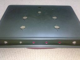
Construction of the amp begins by drilling all the holes. Make sure the chassis is totally free of any metal turnings or grindings before mounting any parts. Next, mount all the transformers using small nuts and bolts, and then mount the valve sockets and the rest of the hardware.
Begin by wiring the mains circuits (mains cable, switch and fuse). As you need to wire all three power transformer primaries in parallel (brown to brown, blue to blue), I suggest you simply wire them together and then tape and heatshrink the joints to be safe. I also recommend that you apply heatshrink to the fuse holder and mains switch for safety.
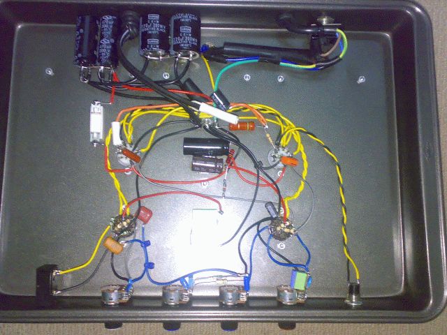
In my prototype, I mounted the power supply capacitors by fixing them with contact adhesive or silicone sealant to the chassis. This allows you to wire the power diodes directly to them.
You need to get the two secondary windings correctly phased so that the two 30V windings add to and not cancel each other – if the total across the series combination is 0V, simply reverse the connections to one of the windings.
I chose to construct the amp by using the valve holders as “tag points” and with a few exceptions, every connection could be made in this way. Where a logical “tag points” was not available, you can simply run a wire from the free component end to the corresponding point in the circuit and anchor the free end with a cable tie to an appropriate anchor point.
To ensure you have the minimum problems with your amp, I suggest you take your time, and check, check and re-check the wiring of each component against the circuit both before you wire it in and after it is in place.
I also recommend that you measure the value of each resistor with a multimeter before you wire it into the circuit to make sure that you haven’t mixed up resistor values.
When you first power up the amp, you should see over +300V available at the main HT supply with the amp idle. Other key voltage checks are approx +11V at the cathodes of the output valves and about half of the HT volts at the anode of each preamp triode. The phase splitter should have around +80V at the cathode and +200V at the anode.Finally connect a speaker and play to your heart’s content!
