
I regularly receive emails with questions about a Hi-Fi valve amplifier design I developed many years ago. The design has been posted on a few websites and I thought it would be a good idea to re-post it here and to add some updated information.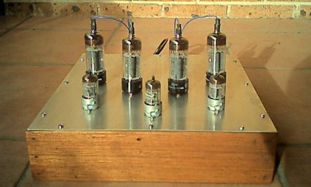
Here is the schematic for the amplifier – click on it for full size.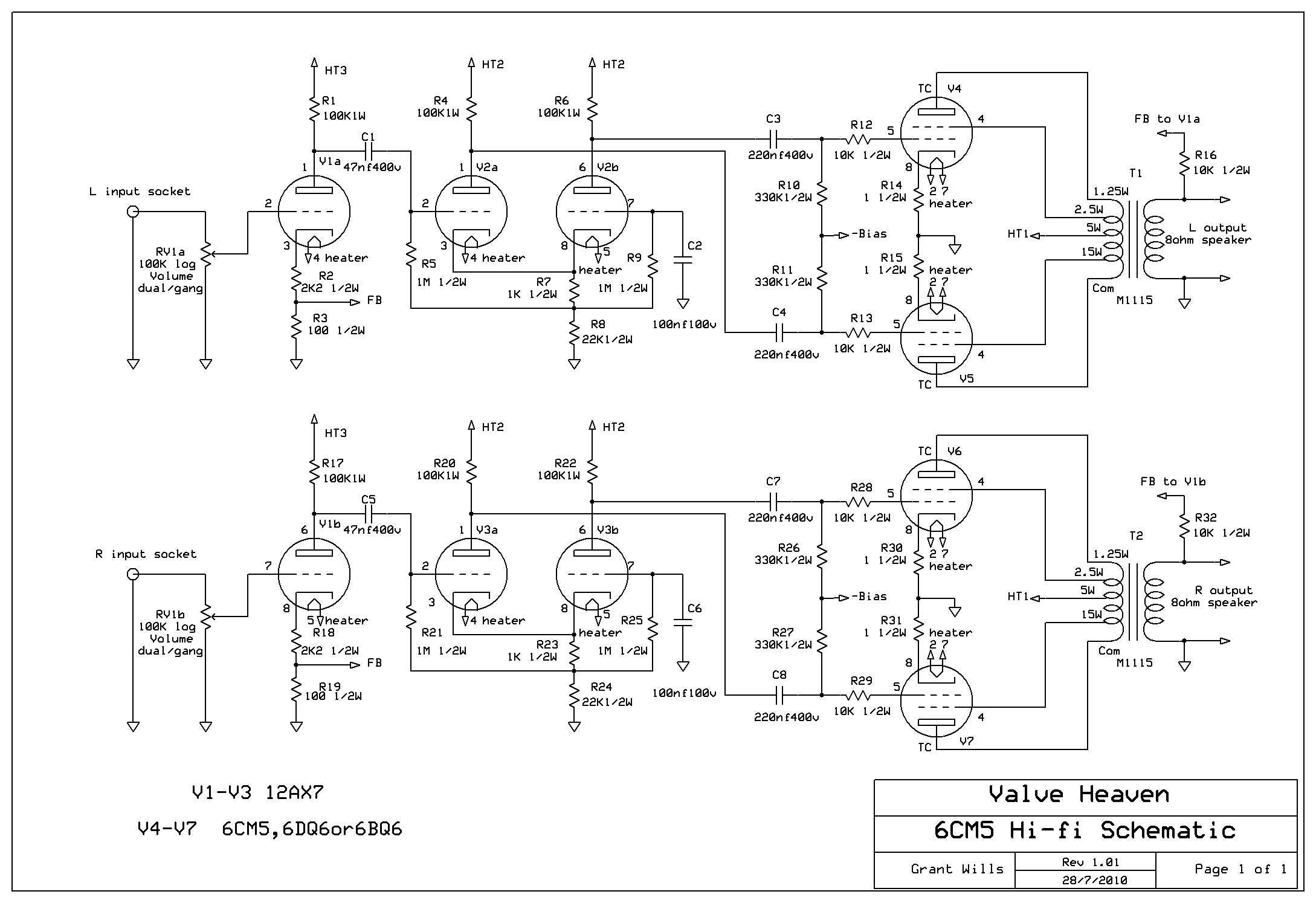
And here is the text that accompanied the original design:
“This is a design for my 15W/channel ultralinear hi-fi stereo amplifier. The front end of the circuit is conventional. The Mullard 5-10 amplifier uses the same phase splitter as I have, and the text refers to it as “a cathode-coupled phase splitter”. The output stage initially used 6L6 valves with a supply of 300V as again I had some on hand, but after quite a bit of experimentation with other output valves I landed on 6CM5 valves.
As is well known, they are an odd valve to be used for audio applications, and I had several unsuccessful attempts to use them. I thought initially that I’d feed the screens with 1/2 B+ as that is how data sheets suggest you should do (and incidentally how similar line output valves such as 6DQ6 are configured in old guitar amplifiers). However, any attempt to use them in this way caused fairly violent oscillation at ultrasonic frequencies. In addition, I wanted to use them in ultralinear configuration and tying the screens at 1/2 supply did not permit this. The ratings indicate a maximum screen supply of 200v and so I hesitated to use the ultralinear mode. However, after trying several configurations which either oscillated, distorted or otherwise misbehaved, I tried them in ultralinear mode with a fairly high amount of bias (-50v), and they worked really well. They were by far the most linear of any valve I tried and worked well with a fairly low standing current (approx 25ma each) and put out the maximum power (17w). This seemed to justify their rather high heater power requirement. So it seems that it is fine to run these valves with higher screen voltages.
The power supply used an old Philips valve power transformer which was up to the fairly high heater current load (4x 1.25A + 3x .3A = 5.9A) and had a ht winding of 110v which applied to a voltage doubler provided 300v HT. I decided to use fixed bias as it allows higher plate to cathode voltage for the output valves than cathode bias. The technique of getting a negative bias voltage from a voltage doubler is an old trick from guitar amplifier designs. I added a 10 ohm resistor in each 6CM5 cathode earth return to monitor cathode current and act as a fuse under overload conditions. Note that the circuit doesn’t have any provision for individual adjustment of output valve standing currents. This was because I used 4 Radiotron 6CM5’s from the same batch with very similar characteristics. A couple of other 6CM5’s that I tried varied a bit in standing current. It may be helpful to modify the bias supply with 4 x 50K trimpots in parallel and then in series with an 82kOhm resistor to ground across the bias supply in place of the one 100kOhm trimpot. With each trimpot wiper independently feeding each output valve this arrangement could then provide individual bias control over each valve. If the bias voltage needs to be increased, the value of the 220nF capacitor feeding the bias rectifier can be increased.
Construction was fairly easy as I took a leaf out of many current hi-fi amp designs. I simply made up a square plinth of timber which has a 12 by 12 inch aluminium sheet (from Dick Smith or Jaycar) fixed to the top. Easy to make and it makes a great furniture piece. I checked the frequency response figures – the amp has a wide frequency response with sustained bass and sounded very nice indeed – even my wife immediately noticed a dramatic difference in sound to our existing solid-state hi-fi amplifier. The S/N ratio for this amp was outstanding – maybe the C-core power transformer, or the star earthing, or the provision of a centre-tap on the heater winding, or my 100µF overkill filter capacitors on the small signal HT? The noise and hum are just about inaudible listening directly to the drivers of my quite sensitive speakers – certainly better than other amplifiers I have used over the years, and pretty amazing for a valve amp! Overall, a lot of fun to build, and a most satisfactory result.“
Here is an underside image of the original design: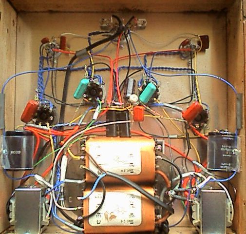
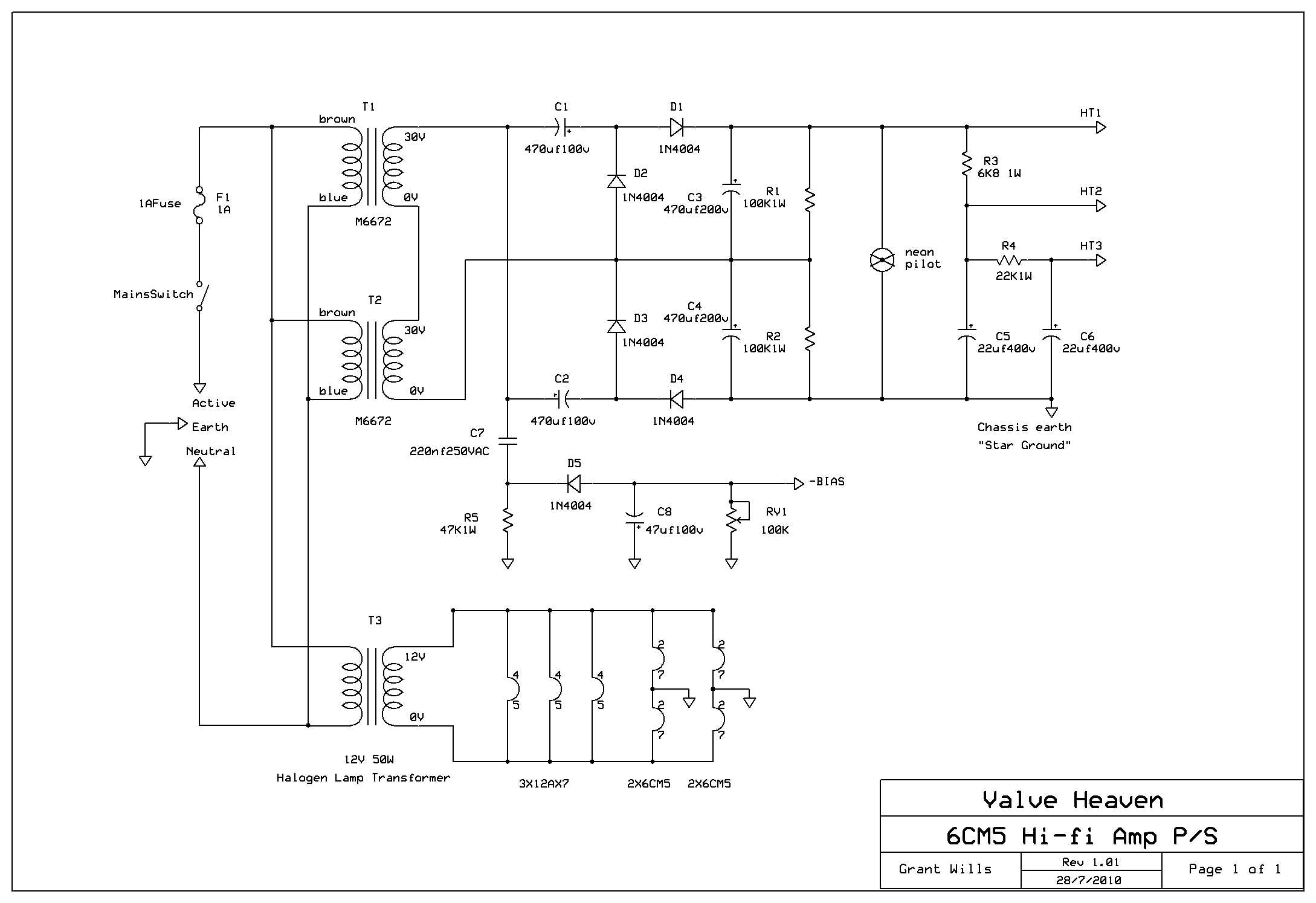
Since I developed this amplifier, I have received many requests for an alternative power supply for the amp. The original used an old TV power transformer which is not available any more and so I looked at an alternative power supply using similar voltage multipliers to my Lamington designs. Here is a schematic for an updated version of the power supply adapted to use currently available transformers here in Australia. Click on it for full size.

I will try to constract your amp.Would you please be kid enough to give me more info about the high voltage transformators?
Hi Dimitri,
Thanks for your interest in my hi-fi amp. The transformers are 30V 1A secondary transformers. A single 60V 1A transformer would work also.
Cheers
Hi Grant
I did build this amp and was a good sounding amp. I had to change the value of C7 to achieve the Bias.
This amp is driving up the price of 6CM5s 🙂
Good work, Keep it up
Hi Daniel,
Great to hear you have built the amp and happy with the result! Cheers
Hi grant my first time,so sorry to see Roly passed,what a great man.you guys have done such a wonderful job of keeping people interested,l’ve thoroughly enjoyed every read .gee talking about 6cm5’s and pa’s l’ve still got 7or so factory pa’s that l’m still trying to get around to eg Phillips stc geloso yes a 100 watt with original el34’s a virgin a zephyr a playmaster 117 etc ,anyway Grant l should have chimed in ages ago but keep up the good work mate cheers: stef .
Hi Stefan, thanks for your kind words!
Thanks a lot for your construction it was rally helpfull and outstanding.I wonder if there is a possibility for tones (Bass-Treble)
Hi Dimitrios,
Great to hear you liked the amp design! Tone controls are only possible if an extra gain stage was to be added. Perhaps the best approach is to use a separate preamplifier?
Grant, firstly thanks for making this design available. I’m planning on building one of these hifi stereo amps to go with a turntable. Have you played a turntable through it, presumably via a phono preamp? If so can you tell me what your setup was. Thanks very much.
Hi Reid,
Thanks for your interest in the amp design. I used it with a CD player making a preamplifier unnecessary. If you wish to use a turntable, you will need a phono preamp as you suggest. Cheers.
Hi Grant,
Been recently taken into the world of Valve audio circuits and loving it.
I have a bunch of 12AU7’s sitting around at home – do you think the circuit could be adjusted to utilise these, or is the gain just not quite there to drive the 6CM5’s?
Cheers
Hi Michael, 12AU7s could be used in my amp, but you would need to change the cathode bias resistors for those valves. Also, the loop gain would be quite a bit lower as the 12AU7 has a mu of 20 vs the 12AX7 with a mu of 100.
Thanks Grant, greatly appreciated.
Would it be worth adding in a 4th “half” of the 12AU7 per channel, to give it a bit of extra gain? Running them at say 10 and 10, to ensure there would be enough drive for the 6CM5s?
That could be done or just try the 12AU7s in the existing design.
Awesome, thanks again.
I dug through my box and found some 6BQ7A’s – these have mu of around 38, so bit warmer than 12AU7s.
Loading these up in LTspice is looking good, so I’ll give it a crack and see how I go.
M.
Hi Grant,
This amp is the best sounding bit of kit I have owned. Treated myself to a pair of Krix floor standing speakers so the neighbors can enjoy it as well..
Used Hammond output transformers and changed the biasing to include 4 multi-turn trim pots. Eltro-Harmonic 12ax7’s give a really clear top end. Pentodes are cheapie ‘Harmony’ EL36 from ebay. They need a hot bias to run clean but at 9 bucks each that’s fine by me. Wouldn’t mind finding a stash of NOS Telefunken 6cm5’s! Added some nixie thermometer tubes to monitor the output (well, sort of).
Paul.
Hi Paul,
Great to hear you are enjoying your 6CM5 amp. The 6CM5/EL36 valves are certainly unsung heroes – they are very linear in triode (or UL) operation, and there are those who describe them as a poor man’s 2A3! Cheers
Found that the $4 Russian 6P31S sounded even better!
Took some fiddling to bias them.. had the odd red plate at the start..
Hi Grant,
I know it’s an old post but I think this is what I was looking for for a long time.
The bias supply modification, you meant?:
V4 V5 V6 V7
I I I I
—-+——-+——–+——+
50k pots
I ______ I _______I _____ I
I
82kohm
I
G
Cheers
Zoltan
This will be my second tube amp after a basic Pilot 232 design, I’m very excited.
Thanks for sharing
Hi Zoltan, yes that is what I suggested for allowing individual bias adjustments for the 6CM5s. Cheers
Found that the $4 Russian 6P31S sounded even better!
Took some fiddling to bias them.. had the odd red plate at the start..
What bias voltage did you finish up putting onto the 6P31S ?
The 6CM5s in my amp needed around -60V of bias. Different valves including the 6P31Ps will vary from that figure. Cheers
Hi Grant,
May I as what the three HT and one Bias voltage rails are please? I am looking at designing up a DC buck supply in lieu of a mains transformer based PSU. Thanks.
Hi Scott, the 6CM5 amp prototype main HT was a little over 300V DC and the derived rails 10-50V less than that.
Hi,
Thanks for the amplifier schematics. I am just a hobbyist and was keen to build my first tube amp after building a couple of solid state amplifiers. I managed to pick up a mixed lot of tubes, many do not appear well suited for audio. There was however 16 x 6cm5 tubes so a quick search brought me here. The price of 12ax7, In Aus anyway, is off the charts. Looking for a cheaper alternative than the 12ax7 :).
Hi Richard, yes the Soviet 6N2P valves are 6.3V heater equivalents to the 12AX7 and can be used if you wire the heaters for 6.3V. They are available cheaply on eBay.
Thats is great, thanks Grant. I have a few 6N2P/6H2N now in stock :). Need to build a tube tester before I get ahead of myself.
Hi Grant,
I have 16 of these tubes that are likely used. I notice there are three different types with either 5, 6 or 7 pins on the bases ? Many of them I measure continuity between 2-7 and 3-8 ? Is this correct?
Hoping to build this amp if any of these tubes are ok.
Richard
Hi again Richard,
The 6CM5 was manufactured by several makers and some valves had more pins than others. Just be aware that some have pin 3 connected to pin 8 as you have discovered. Pin 3 is normally the plate connection in octal power valves.
Hi Grant, great anp and write up..
I had a large stash of television valves do decided to use some EL36s and ECC81s for front end, and it sounds great!
Unfortunately my valves vary a little in anode current so wanted to do the suggested modification for individual grid biasing.
My question is.. do I remove the two 330k resistors on the bias input and feed the wipers from each pot directly into each grid?
Apologies for the newbie question..
Many thanks
Adam
Hi Adam, good to hear you are enjoying your amp. The 330K resistors need to remain in circuit – join each 330K resistor to the wipers of each bias pot.
Hi Grant..
Thanks for your advice, that’s exactly what I did, and added the four trim pots, and have all four EL36s sat at 25ma, and sounds fantastic!
My screen voltages seem a little high, 320v at volume half way.. would you say this is to high?
Apologies for the newbie questions, I’d just rather not ruin brand new tubes!
Although I do have a large stash of mullard PL36s but would need a 25v heater trans.
Thanks again for your advice..
Cheers
Adam
Hi Adam, good to hear. The screen voltage of 320V is higher than the datasheet values, but in an ultralinear or triode mode it is ok as the screen voltage tracks the anode voltage meaning that screen dissipation is not exceeded.
Hi Grant.
Thanks for all your advice,
Now to build a phone stage!
Hi Grant..
Would you by any chance have a phono stage build with schematic?
I’ve looked at a few online and none are as easy to follow as your schematics!
I was hoping to use 12AT7 tubes as I have a few kicking about.
Thanks again.
Adam.
Hi Adam, no I have not developed a phono preamp for my amplifier.
Hi Grant..
No worries, I’ve found a simple design and built it, but it lacks bass response, so having rather a head scratcher now.
RIAA Equalisation most likely missing. You need a RIAA “analog decompressor” to restore the bass, wich has been reduced by a fixed value to fit low frequency onto a record without creating superwide, superdeep grooves as if not reduced. The restoring is done by resistor-capacitance and resistor-inductance networks depending on design.
Thank you Michael,
You are absolutely correct, it was a very basic design which I have now changed using with a RIAA circuit,
Which combined with Grants amp sounds superb,
Hi Grant
I want to build the amplifier.
There are no M115 or similar line output transformers in Argentina.
But there are output transformers for different output tubes, push-pull, single-ended, and with different primary load impedances.
Please tell me the value of the primary plate-to-plate load resistance and the percentage for the ultralinear connection.
I look forward to your kind response.
Thank you very much.
Gustavo
Hi Gustavo, thanks for your interest in my amp design. The M1115 transformers used in my amp reflected an 8K plate to plate load impedance with an 8 ohm speaker. The screen taps worked out close to the 43% typical of ultralinear operation. Hope that assists!
Thank you very much Grant for your help.
Best regards
Gustavo
Helo Grant, I appreciate the open state hi-fi amp diagram, it is not easy to find open state tube amp diagrams these days and it’s good to see someone is keeping the art alive. I would love to build your amp if you can post a parts list, it would be much appreciated.
4K5 laboratorys O.N
Hi Arthur, thanks for your comments. I don’t have a parts list for this design, but the schematic and the description should provide the relevant parts info.