Introduction I Design I Construction
A kit of all parts, and a construction manual for the Lamington Junior are now available!
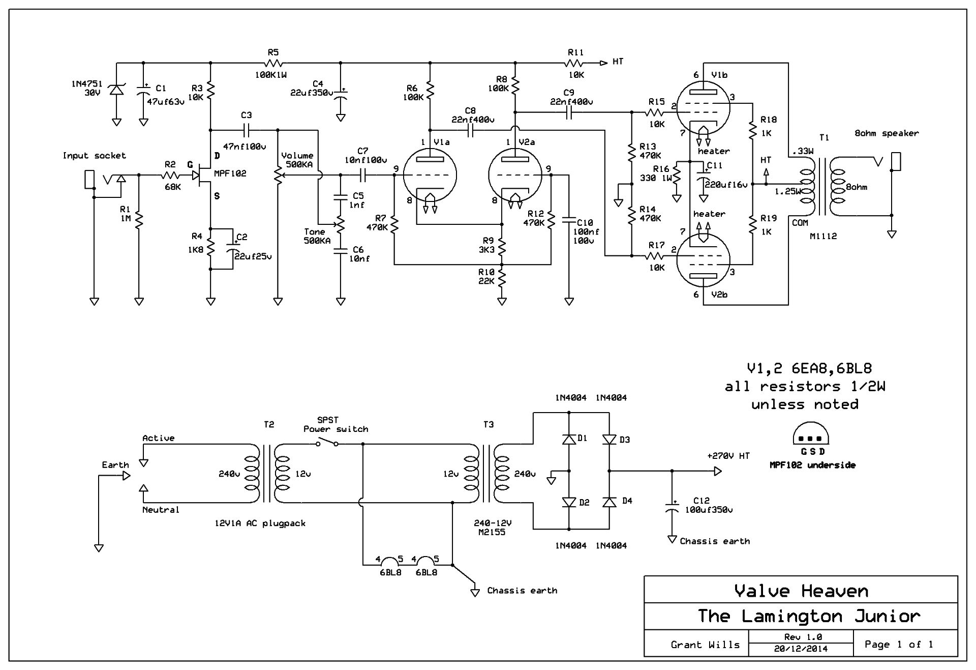
The schematic diagram of the Lamington Junior can be seen below. It uses a pair of 6BL8 valves which contain a triode and pentode in the one envelope. The triode sections are configured as a “long tailed pair” phase inverter driving the pentode sections as a push-pull output stage. 6BL8 valves were used extensively in B/W TV sets and are pin compatible and interchangeable in this design with a heap of other valves – 6U8, 6GH8, 6EA8, ECF80, ECF82, ECF802, 6JW8, 6CQ8, 6KD8, 6F1P, 6LX8, 6MG8. All of these valves can be used in the Lamington Junior and some have different gain/characteristics to the 6BL8 allowing for differing tone/drive options. These valves are readily available from the Internet as they were made by the millions and extensive stocks are still available.
What is a little unconventional in the Lamington Junior is the use of a FET (field effect transistor) in the preamp section. Several preamp configurations were prototyped during development, and the FET held its own against a pentode preamp, and sounded better than a triode preamp. FETs have been used in the past in the input stage of Acoustic and Mesa Boogie amps and operate in a similar way to a pentode valve with similar transfer characteristics. The use of a FET preamp in the Lamington Junior also simplifies construction and reduces power supply requirements.
The power supply for the Lamington Junior uses a 12V1A AC plugpack to supply the valve heaters in series and to drive a 12V to 240V transformer to provide HT for the amplifier. The benefit of this arrangement is that it eliminates contact with the 240V mains making this amp safer to build.

