Design | Construction | Components
The design for the Lamington amp is conventional with the exception of the power supply, which uses some unorthodox techniques to develop the +300 volt high tension supply.
The design objective was to provide a 18W output which is typical for medium power “boutique” amps.
Output Stage
Referring to the circuit diagram above of the Lamington and looking at the bottom right of the diagram you can see the output stage. There are two power valves in the output stage in what is called a “push-pull” configuration. This allows the valves to provide the maximum power possible.
These two valves need to be driven in different directions (called “out of phase”) so that as one valve is driven harder, the other valve is turning off. You can see that each valve anode connects to each end of the output transformer primary winding with the +300V high voltage applied to the centre tap of the transformer. The secondary winding of the transformer drives the speaker.
In the long distant past, such an output transformer was readily available. However, these days these transformers have only been available by special order from overseas and have been very expensive. This amp however, uses a readily available and cheap transformer that is normally used as a “line transformer” for PA speakers.
Phase Splitter
To the left of the two power output valves is a triode valve called a phase splitter. The purpose of this phase splitter is to provide out of phase signals to drive the two output valves. The phase splitter is configured so that the signals at its anode and cathode are out of phase with each other. These signals are applied to the grids of the two output valves to provide the “push-pull” drive required.
Preamplifier
Located at the top of the circuit diagram is the preamplifier, or “front-end” of the amplifier. Note that each of the three stages or “valves” in the preamp is in fact one half of a 12AX7 dual triode valve.
The input signal from a guitar is applied to the grid of the first stage. At the anode of this first stage there will be an amplified version (gain) of the input signal. This is applied to the first volume control (marked the drive control) which together with the master volume allows the preamp to be set up for clean or distortion operation of the preamp.
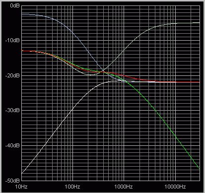
From the drive control, the signal is applied to the second stage. From the anode of this stage, the signal is applied to the frequency selective tone controls (sometimes called the “tonestack” or “EQ”) which provide bass and treble boost and cut using the typical “James” arrangement.
The output of the tone control is applied to the grid of the third preamp stage which drives the master volume control.
Power Supply
The amp design is quite conventional, with the exception of the unorthodox output transformer, and has been used since the 1940s with a few different variations.
The power supply, however, is unconventional but very effective in it’s role to provide the high voltage required for the valves. In the past, high voltage transformers suitable for a valve amp power supply were readily available, but are no longer available except by order at a high cost from overseas. Rather than use such an expensive, difficult to obtain high voltage transformer, we are using two cheap, readily available low voltage transformers to provide the high voltage.
Looking at the power supply circuit, you can see how this is done.
Two inexpensive readily available 30 volt transformers have their secondary windings connected in series to provide a total voltage of 60 volts AC. This 60v is applied to a voltage quadrupler (alternatively called a charge pump) which multiplies the voltage to over +300 volts.
Just in case you think that we are getting something for nothing, the current that can be drawn from the 300V supply is only a quarter of the current available from the transformers combined 60V input. As the transformers are capable of 500ma of current, with the resulting output limit of (500/4 = 125mA) they can easily supply the 100ma of current required from the 300V supply.
The valves also need 6.3V for their heaters which is provided by a third low cost transformer.

